Re: Far too much gain
Just like this?
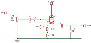
EC8010 said:All you need is the cathode follower to buffer the volume control. To do that, you need to remove the first stage, and insert a 2k2 resistor between the cathode and the existing 100k cathode resistor, then take a 1M resistor from this junction to the grid. (And add a 1k grid-stopper to the cathode follower to prevent RF oscillation.) Finally, connect the grid to the volume control via a 10n 400V capacitor.
Just like this?
Attachments
Now I am smiling 
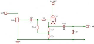
Changed circuit as suggested by EC8010, all problems solved. So I ended up with not an "Improved Audionote M7 Clone" - but still a very good sounding preamp (or rather just a buffer). It does the job and I like it. Thanx again to EC8010, Frank and all others for your advice and assistance. Much appreciated
Now what to build (try) next??
Final circuit:
Attachments
Hi,
You can still improve on this one but it kind of proves what people like EC8010, Brett and myself have advocated for the past years...
Glad you like it.
Cheers,
EC8010, Frank and all others for your advice and assistance. Much appreciated
You can still improve on this one but it kind of proves what people like EC8010, Brett and myself have advocated for the past years...
Glad you like it.
Cheers,
Glad you like it.
I'm impressed. You modified it pretty damn quick. If you were driving a transistor amplifier, I'd say, "parallel the two valves and halve the resistor values," but you're not, so I suspect you will get better quality by grounding all the second valve's electrodes and leaving the first valve as it is.
I'm impressed. You modified it pretty damn quick. If you were driving a transistor amplifier, I'd say, "parallel the two valves and halve the resistor values," but you're not, so I suspect you will get better quality by grounding all the second valve's electrodes and leaving the first valve as it is.
To me it always seems "wasteful" to use only half a tube. Why not use both halves of a single 6072, one for each channel?
Or use the remaining half as an active load for the follower? Your B+ is sufficient and all you'd really need to take into account is the max permissible V(hk)... requiring only an R-R network to float the filaments at an acceptable voltage - say +80v. Best to check the 6072 datasheet for V(hk) limits though...
Another possibility to try would be the so-called "White cascode" configuration. If memory serves the tubecad website has plenty lowdown on these and other configs...
DrG said:To me it always seems "wasteful" to use only half a tube. Why not use both halves of a single 6072, one for each channel?
Or use the remaining half as an active load for the follower? Your B+ is sufficient and all you'd really need to take into account is the max permissible V(hk)... requiring only an R-R network to float the filaments at an acceptable voltage - say +80v. Best to check the 6072 datasheet for V(hk) limits though...
Another possibility to try would be the so-called "White cascode" configuration. If memory serves the tubecad website has plenty lowdown on these and other configs...
If not, why not ?

I am catching a like in these glass things and can only see it as a way to learn more and in the process maybe improving my sound system.
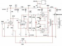
So looking at the attached pic. , how do I then calculate Ra and Rk? It IS the White Cathode Follower - just drawn a little bit other wise
B+ can be reduced if needed.Attachments
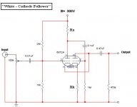
Your fixed bias White cathode follower injects power supply noise directly into the signal, which is not ideal. If you lose that potential divider but add a cathode bias resistor in series with the first cathode, you can take a 1M grid-leak resistor from the grid to its lower end, and this will reject power supply noise. The cathode bias resistor will be the same value for both valves. The anode resistor should be 1/gm for maximum output current.
EC8010 said:Your fixed bias White cathode follower injects power supply noise directly into the signal, which is not ideal. If you lose that potential divider but add a cathode bias resistor in series with the first cathode, you can take a 1M grid-leak resistor from the grid to its lower end, and this will reject power supply noise. The cathode bias resistor will be the same value for both valves. The anode resistor should be 1/gm for maximum output current.
O.K. So I basically use Frank's circuit with differant Ra and Rk.
Can this be correct for Ra and Rk?
Attachments
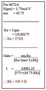
Well, I can't imagine how a number for gm can just be plucked out of the air without considering the operating point, and I certainly don't agree that a value for a DC bias component can be derived from an AC equation.
You have 300V to spend, across a pair of identically biased valves, so each valve receives 150V. A 6072 typically only needs a few volts across the cathode bias resistor, so we can approximate, and say Va = 150V. Looking at the curves, choosing 2V of bias would result in 2.65mA of anode current. By Ohm's law, 2V/2.65mA = 750R, so that's your cathode bias resistor. A different choice of operating point would give a completely different value for Rk...
Drawing a tangent to the 2V grid curve at the operating point gives ra = 20k. Drawing a horizontal line at the operating point to find mu, gives mu = 46.5. gm = mu/ra = 46.5/20 = 2.3mA/V, so 1/gm = 430R.
EC8010 said:A 6072 typically only needs a few volts across the cathode bias resistor, so we can approximate, and say Va = 150V. Looking at the curves, choosing 2V of bias would result in 2.65mA of anode current. By Ohm's law, 2V/2.65mA = 750R, so that's your cathode bias resistor. A different choice of operating point would give a completely different value for Rk...
Drawing a tangent to the 2V grid curve at the operating point gives ra = 20k. Drawing a horizontal line at the operating point to find mu, gives mu = 46.5. gm = mu/ra = 46.5/20 = 2.3mA/V, so 1/gm = 430R.
Is it possible to sent me these curves/graphs on the 6072A - please ? I really want to get to know this thermionic emision stuff better.

Just go to Frank's site, and you will find all the valve data you will ever need:
http://home.wxs.nl/~frank.philipse/frank/frank.html
http://home.wxs.nl/~frank.philipse/frank/frank.html
EC8010 said:Just go to Frank's site, and you will find all the valve data you will ever need:
http://home.wxs.nl/~frank.philipse/frank/frank.html
This 1 works
Frank's Site
Follow up
After a couple of months now, I decided to see if I can get rid completely of my LF oscillation problem (in my 1st post) and still use the org. circuit with my Mullards. I again looked at all the advice form our fellow tube guys, and reconstructed the org. circuit. The LF problem was still there as in the beginning. Then I got the idee of grounding the top plate, on which my valves are mounted, to the star ground point. This is the only thing I did not try previously. What an improvement. I don't know why I did not try it right in the start 
The LF oscillation is still there but at about 1/4 amplitude of what it was.
In the mean time I also build a subwoofer with own amp and controler (filter with volume) . The way I use it with rest of system is to T-off from just after pre-amp to subcontroller. So I did same now with tube pre-amp / Mullard combo.
Now this is where it gets very interesting (to me anyway) Since I connected sub controller to output of pre-amp. LF oscillation is virtually gone. With naked eye I can see no movement what so ever on cones. I am not sure what the downside of my subcontroller hookup to pre-out is, but in the sound of the system, it is just fantastic. This is the sound I expected from this pre-amp when I decided to build it.
Now I am happy and can really reccomend this pre-amp, easy to build - if you don't have LF oscilations , really very good sound.
Attached is circuit to show my pre-amp / sub controller / Mullard's interfacing. Please advice on better way to do this, if needed.
Thanx again to all who helped / still helping
After a couple of months now, I decided to see if I can get rid completely of my LF oscillation problem (in my 1st post) and still use the org. circuit with my Mullards. I again looked at all the advice form our fellow tube guys, and reconstructed the org. circuit. The LF problem was still there as in the beginning. Then I got the idee of grounding the top plate, on which my valves are mounted, to the star ground point. This is the only thing I did not try previously. What an improvement. I don't know why I did not try it right in the start
The LF oscillation is still there but at about 1/4 amplitude of what it was.
In the mean time I also build a subwoofer with own amp and controler (filter with volume) . The way I use it with rest of system is to T-off from just after pre-amp to subcontroller. So I did same now with tube pre-amp / Mullard combo.
Now this is where it gets very interesting (to me anyway) Since I connected sub controller to output of pre-amp. LF oscillation is virtually gone. With naked eye I can see no movement what so ever on cones. I am not sure what the downside of my subcontroller hookup to pre-out is, but in the sound of the system, it is just fantastic. This is the sound I expected from this pre-amp when I decided to build it.
Now I am happy and can really reccomend this pre-amp, easy to build - if you don't have LF oscilations
, really very good sound.Attached is circuit to show my pre-amp / sub controller / Mullard's interfacing. Please advice on better way to do this, if needed.
Thanx again to all who helped / still helping
Attachments
- Status
- This old topic is closed. If you want to reopen this topic, contact a moderator using the "Report Post" button.
- Home
- Amplifiers
- Tubes / Valves
- 6072A Line-Amp