(Follow up on this - http://www.diyaudio.com/forums/showthread.php?postid=242559#post242559 )
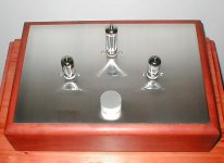
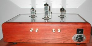
I just completed this one and got some final measurements and some questions. I used a nice solid Rhodesian Rose Wood for chassis with stainless steel top and copper cladding on inside. Alps Blue pot and Holco resistors. Input and output wires are some left overs from "Van Der Hull" and "Nordost" interconnects. Main trafo and separate heater PSU trafo are in separate box , connected with 8 core umbilical to pre-amp box. Still using mixed brand 6072's , but are very pleased with sound.
1) Except for lefthand 20H choke - still old one - all other chokes and trafos are new, but I still get low frequency oscillation on speakers when using 6072 with Mullard 5-20 - why? But no problem with SS amp
2) How can I fix this problem ?
Here is my voltages and other notes and some pics:
Attachments
Hi,
Do I read this correctly?
The preamp + Mullard amps goes into LF oscillation but the same preamp and SS amps works fine?
To my logic I'd then conclude something's wrong with the Mullard amp but obviusly you don't seems to think so...
Cheers,")
but I still get low frequency oscillation on speakers when using 6072 with Mullard 5-20 - why? But no problem with SS amp
Do I read this correctly?
The preamp + Mullard amps goes into LF oscillation but the same preamp and SS amps works fine?
To my logic I'd then conclude something's wrong with the Mullard amp but obviusly you don't seems to think so...
Cheers,
Motorboating?
You'd be surprised, but at low levels many valve amplifiers have lower f-3dB points than their transistor counterparts. The problem you describe sounds like motorboating, but that seems unlikely in your pre-amplifier circuit, so what frequency (estimated) are we talking about? 1Hz-2Hz?. The only thing I can presently see that looks odd is that you are using raw HT to set the elevation of your heater voltage, rather than filtered HT. I can't see how this could cause motorboating, but it's definitely not a good idea...
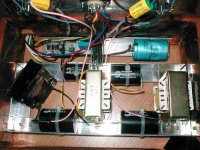
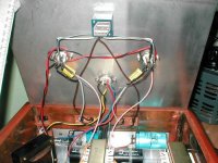
Edit: I've just taken a closer look at your photographs, and although I'm delighted to see a variac lurking in the background for a gentle start-up, I'm not so happy with your layout. Why are those two signal valves so far apart, and why are their associated components so far away? Audio components belong on the valve bases. Power supply stuff belongs further away. I know you have DC heaters, but the twist and layout of your heater wiring is not good.
You'd be surprised, but at low levels many valve amplifiers have lower f-3dB points than their transistor counterparts. The problem you describe sounds like motorboating, but that seems unlikely in your pre-amplifier circuit, so what frequency (estimated) are we talking about? 1Hz-2Hz?. The only thing I can presently see that looks odd is that you are using raw HT to set the elevation of your heater voltage, rather than filtered HT. I can't see how this could cause motorboating, but it's definitely not a good idea...
Edit: I've just taken a closer look at your photographs, and although I'm delighted to see a variac lurking in the background for a gentle start-up, I'm not so happy with your layout. Why are those two signal valves so far apart, and why are their associated components so far away? Audio components belong on the valve bases. Power supply stuff belongs further away. I know you have DC heaters, but the twist and layout of your heater wiring is not good.
Do I read this correctly? The preamp + Mullard amps goes into LF oscillation but the same preamp and SS amps works fine? To my logic I'd then conclude something's wrong with the Mullard amp but obviusly you don't seems to think so...
No, not that I don't think so, it is quit possible. I just don't understand why it happens and how to solve it. Because if I use SS preamp with Mullard, all behaves very well.
Edit: I've just taken a closer look at your photographs, and although I'm delighted to see a variac lurking in the background for a gentle start-up, I'm not so happy with your layout. Why are those two signal valves so far apart, and why are their associated components so far away? Audio components belong on the valve bases. Power supply stuff belongs further away. I know you have DC heaters, but the twist and layout of your heater wiring is not good.
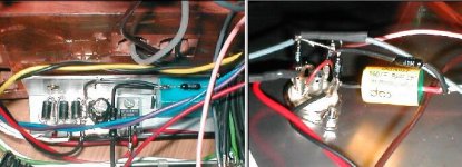
All audio related components are on valve bases (pic.2) , other stuff down in box (pic.1) is for DC heater supply. It is difficult to measure, but oscillation is between 1Hz and 5Hz. It varies all the time. The 2 signal valves are for left and right channel. I used both sides of 6072A / channel . Is it importand that L and R must also be very close together? The twist in wire is only to keep them together, not really for any other reason. I can untwist and use cable ties instead if it will be better.
(2 pics in 1)
Attachments
Well, you should do the obvious first - have PS decoupling close to the valves; keep input and output wiring well separated; follow a sensible star-earthing scheme - have separate earths for PS and amp and join them in one point. Sorry if you've already done this - i really hate staring at photos.
It's not important to keep channels close together per se, but it keeps the earth wiring to the common power supply under control.
Assuming you have access to an oscilloscope:
Is the oscillation leaving the pre-amplifier? (DC couple the oscilloscope)
Is the heater supply stable?
Is the HT supply stable? (AC couple the oscilloscope)
As analog_sa says power supply decoupling close to the valves and star earthing usually avoids most problems.
JDeV said:I just completed this one and got some final measurements and some questions. I used a nice solid Rhodesian Rose Wood for chassis with stainless steel top and copper cladding on inside. Alps Blue pot and Holco resistors. Input and output wires are some left overs from "Van Der Hull" and "Nordost" interconnects. Main trafo and separate heater PSU trafo are in separate box , connected with 8 core umbilical to pre-amp box. Still using mixed brand 6072's , but are very pleased with sound.
For more nice projects and good tube stuff, visit Dick's site here: Thanx for all of this Dick

http://www.triodedick.com/
EC8010 said:Is the oscillation leaving the pre-amplifier? (DC couple the oscilloscope)
Is the heater supply stable?
Is the HT supply stable? (AC couple the oscilloscope)
As analog_sa says power supply decoupling close to the valves and star earthing usually avoids most problems.
Some more info:
I did notice that low F oscillation is already present just after 10uF cap on HT supply. Still don't know why.
I use a good star ground layout to start with, so that is o.k.
I did couple of things today which all helped to reduce the problem, but not solve it.
1) Fit 1uf OSCON on tube bases over dc heater supply.
2) Rerouted rectifier tube supply and HT.
3) Changed 33uF supply caps to 120uF - is this O.K. - not too much for valves?
4) Fit "silent" HT trafo - not making any vibrating noises.
5) Fit 600ohm resistors on 230-0-230 supply lines to reduce HT supply down to 290V. (Was 315V dc with "silent" trafo.)
The output signal is now very stable with small 50Hz AC component and very small low F oscillation. Can not hear or see it at all on SS amp (unless putting ear right inside speaker almost), but Mullard's are still not happy with it. I guess I should now start to work on them, or what do you think - Frank
Questions:
1] The EZ81 is making a physical vibrating sound, is it normal? Can hear it from about 1/2m away when no other noise in room.
2] Can I use DC for EZ81 heater supply, or is it bad practice for rectifier tubes?
3] How much capacitance can you put on supply for 6072A?
Thanx for all advise up till now
Hi,
Definetely NOT normal. Have you tried another EZ81?
You can, it's not bad practice but it's absolutely unnecessary.
As much as you like but that's not going to solve anything.
The only thing I can think of right now is that I find it odd, really odd....
Cheers,
1] The EZ81 is making a physical vibrating sound, is it normal? Can hear it from about 1/2m away when no other noise in room.
Definetely NOT normal. Have you tried another EZ81?
2] Can I use DC for EZ81 heater supply, or is it bad practice for rectifier tubes?
You can, it's not bad practice but it's absolutely unnecessary.
3] How much capacitance can you put on supply for 6072A?
As much as you like but that's not going to solve anything.
I guess I should now start to work on them, or what do you think - Frank
The only thing I can think of right now is that I find it odd, really odd....
Cheers,
1] The EZ81 is making a physical vibrating sound, is it normal? Can hear it from about 1/2m away when no other noise in room.
2] Can I use DC for EZ81 heater supply, or is it bad practice for rectifier tubes?
3] How much capacitance can you put on supply for 6072A?
Making an EZ81 buzz is amazing! Mind you, I've never loaded one with 120uF. The manufacturer's maximum is 50uF.
Of course you can use DC heaters on an EZ81. Can't think why anyone would want to, mind.
Two thoughts:
You have an HT supply that splits between channels. I wonder if the motorboating (oh yes, that's what it is) is circulating between the channels. Try removing one 6072 and see if the other channel suddenly behaves itself.
Another possibility is that the heater/cathode insulation on your EZ81 is poor. If you have another, or even an EZ80 (perfectly adequate for your circuit), give it a go.
Hi,
And they're not.
Loaded with a 120µF cap that is, that cap is after the choke.
Possible, but I still suspect a dodgy rectumfrier....
Cheers,
Making an EZ81 buzz is amazing! Mind you, I've never loaded one with 120uF.
And they're not.
Loaded with a 120µF cap that is, that cap is after the choke.
I wonder if the motorboating (oh yes, that's what it is) is circulating between the channels.
Possible, but I still suspect a dodgy rectumfrier....
Cheers,
That EZ81 is much quiter now, can hear it still but with ear right next to it.
This whole LF oscillating thing, could it be because of impedance differances: 6072a --> Mullard5-20 ?
I remember that the "Improved Audionote M7" (As per Robert Ang - http://www.audio-genesis.com/casanova.html )
was stated to have an output impedance of 425ohm, what the input impedance of Mullard5-20 is , I don't know, neither how to measure or calculate it.
How do you measure/calculate these impedances?
No. If you can see something going on at the HT, then the problem is firmly within the line stage.JDeV said:This whole LF oscillating thing, could it be because of impedance differences: 6072a --> Mullard5-20?
The input impedance of a Mullard 5-20 is 1M//<10pF. In transistor terms, that's an open-circuit.
LF oscil. progress
I got hold of scope and actually traced LF origin back to B+. It starts just after 10H choke (where I pick it up for 1st time). In meantime I moved chokes also to seperate box and increased 33uF caps to 470uF. I also replaced EZ81 with normal diodes. This all helped alot , but there is still small amount of LF oscil. Something else that I noticed now, is that there are more hiss, I can actually hear from my listening chair when vol. is turned right down. Also when preamp POT is only 25% open, Mullard is already at max. ouput. How can I reduce sensitivity (gain) ?
Except for these little pains, this preamp really sounds amazing, both with SS amp and valve amp. Can recommend definately.
Far too much gain
The sensitivity of the Mullard 5-20 is 220mV for full power. A few quick calculations suggest that the pre-amplifier has a gain of about 18, resulting in a sensitivity of 12mV for full power at the volume control. Even particularly weedy tuners produce 100mV, so it's no wonder you have hiss and overload once the volume control reaches 10 o'clock.
You just don't need that gain stage. All you need is the cathode follower to buffer the volume control. To do that, you need to remove the first stage, and insert a 2k2 resistor between the cathode and the existing 100k cathode resistor, then take a 1M resistor from this junction to the grid. (And add a 1k grid-stopper to the cathode follower to prevent RF oscillation.) Finally, connect the grid to the volume control via a 10n 400V capacitor. This will get rid of all your superfluous gain, and will probably sound even better. It certainly won't hiss any more.
- Status
- This old topic is closed. If you want to reopen this topic, contact a moderator using the "Report Post" button.
- Home
- Amplifiers
- Tubes / Valves
- 6072A Line-Amp