
Yes, you can make good and bad amps both ways. Given the big temperature changes I would expect a valve amp to be a bit more reliable when wired P2P as this gives more flexibility to cope with thermal expansion. However, for the inexperienced constructor a well-designed PCB (designed by someone experienced i.e. a kit) might avoid some problems.
PCBs are okay if you can squeeze in that extra large can cap you wanted to. Point to point without helping hands or at least a Panavise is just horrible to work with.
I would have to say if you like to swap things out and mod/change/swap things around to change whatever you are outputting, then so long as the copper trace is a good one on a nice PCB, than a PCB it is is easier than point to point.
Point to point done well, can really look like a masterpiece sculpture.
Otherwise, I can't tell the difference if two amps were done with in one of each.
Ptp certainly. Especially if on a teflon board using good quality stand-offs. Not sure if it's because of the vibrational properties of the board or the wire with better dielectric - i mostly use copper/silver inside teflon or cotton tubing. Not to mention shorter connections and better star earthing.
Given a good layout (either P2P or PCB) there shouldn't be any performance difference between the two. However, there are many ways to screw up and arrive at a poor layout. I put considerable effort into the PCBs I make to ensure good signal integrity.
For making several identical circuits, PCBs can't be beat. For prototyping, P2P is rather nice.
I tend to prototype in P2P rat's nests (i.e. not optimal layouts by any stretch of imagination) and notice the mains hum drop significantly when the circuit is transferred to a PCB.
~Tom
For making several identical circuits, PCBs can't be beat. For prototyping, P2P is rather nice.
I tend to prototype in P2P rat's nests (i.e. not optimal layouts by any stretch of imagination) and notice the mains hum drop significantly when the circuit is transferred to a PCB.
~Tom
Point to point has the theoretical advantage if you build tight and in 3D. You can cross opposing signal paths perpendicular as well as having very short leads. It will also be nearly indestructable. But it sure makes a crows neest and often not as mod-friendly.
PCB can be good too.
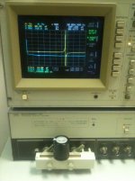
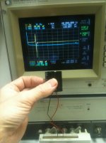
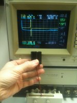
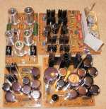
Either way, here are some shots done on the analyzer of a 390uF/450V electrolytic with and without 5inch wires. Note how the resonant frequency goes from 65kHz without wire, to about 15kHz with straight wire and back up to about 25kHz with the same wires twisted.
PCB can be good too.
Either way, here are some shots done on the analyzer of a 390uF/450V electrolytic with and without 5inch wires. Note how the resonant frequency goes from 65kHz without wire, to about 15kHz with straight wire and back up to about 25kHz with the same wires twisted.
Attachments
Once-Upon-a-Time...our old radios & fledgling Hi-Fi were all wired P2P.....no components yet existed, that were small enough to warrant such a creation as the..........Printed circuit-board. Circuit-boards are for mass production.....thousands, millions, billions??
Have you seen the hi-speed PCB productions??.... besides, crafting boards are very messy affairs. Having someone do it for you is great until you find out he/she won't make less than 10,000 of them.
P2P can be utterly magnificent works of art. Now this all depends on how complex your build is.....& how much room you've allocated. Nothing looks worse than a complex build in a chassis that's half as big as it should be....that's where the little scampering critters come out.
________________________________________________________Rick..........
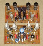
I have done 2 amps with all in one with PCB's (EZ10 and EZ260 search) I have also built and rebuilt a few Dynaco's that are hybrids. Some people like the vintage look of PP wiring and some don't care as long as it sounds good.
The cost of the one off PCB's can be more expensive as well as more difficult to fix errors if you make one that is parts placement or track placement oriented, i.e. routing filament too close to something etc. Toss in thicker PCB or High Temp material and it's nutty.
On the flip side assembly is very quick and makes for a tidy project if others want to build the same thing.
I have been lucky on the 2 PCB's that I made, each had only one easy to fix glitch.
I think one challenge is fitting components in a 2D space while keeping things small and traces where they should be, but hey that's also some of the fun part!
Sandy
IF you have mastered the toner transfer method of PCB's they are simple and easy to fab. You must be wise in layout to prevent cross talk/unwanted feedback, and parasitic capacitance or inductance from interfering with the design intent. Tube PCB's are much easier than bipolar IC designs where you must also consider monolithic thermal feedback into the design as well.
I use the green floral foam to pre-stuff a paper layout of the amp to verify correct component spacings after I've started to scrounge the components. I cannot mount the caps to the back side on paper, but their mounting requirements can be verified.
It is interesting that the space flight electronics that I worked with were duroidal and PCB based circuits, not PTP component wiring. It had the greatest thermal swing from the very cold vacuum of space to full radiation exposure as well as having to survive the G's of launch. MTBF was maximized. PTP component wiring was required prior to the development of reliable PCB materials. Done correctly they are pieces of functional art and should not be hidden in the bowels of a chassis.
There are many ways to accomplish the same goal, to each their own.
Attachments
I hate PCB in tube amplifiers. I have bought several used/old tube amps, and I think 99% of them had some bad connection between the tubesockets and the PCB. There is "always" brown spots on the PCB because of the heat. When you change a tube, you use some force to take the tube out of the socket. The solderpoints on the sockets will often break into pieces, if this is a old amp. Use P2P !!, much easier to build, and to modify the amp...later.
Point to point has the theoretical advantage if you build tight and in 3D. You can cross opposing signal paths perpendicular as well as having very short leads. It will also be nearly indestructable. But it sure makes a crows neest and often not as mod-friendly.
PCB can be good too.
Either way, here are some shots done on the analyzer of a 390uF/450V electrolytic with and without 5inch wires. Note how the resonant frequency goes from 65kHz without wire, to about 15kHz with straight wire and back up to about 25kHz with the same wires twisted.
This is very interesting!
I am all for point to point over a badly designed PCB. You have hum pickup, you move the resistor a little to the side. Try doing that on a PCB.
Nice!SemperFi said:here are some shots done on the analyzer of a 390uF/450V electrolytic with and without 5inch wires.

In 1957, Juke box manufacturer Seeburg produced two models, KD200 and l100. In previous years, all models were PTP using tubes. Due to the many issues
surrounding cracked circuit paths, caused by heating and cooling, this was the only
year circuit boards were used with tubes. Seeburg continued with circuit boards, after
transistors were used for amplification and control, several years later.
surrounding cracked circuit paths, caused by heating and cooling, this was the only
year circuit boards were used with tubes. Seeburg continued with circuit boards, after
transistors were used for amplification and control, several years later.
I cant respond this question, but you will no want a PCB amp:Hi,
Sonically which are better amps, ones that are p2p wired or pcb based?
= if the tube is a big triode or 6C33 as these tubes cook the PCB in few time.
Even pre-amps PCBs will be cooked over the years, as a Class A solid state amp;
= PCB tracks never are silver solder, but raw solder or even lead.
= PCB equips never allow change the circuit, unless you re do the PCB...
= P2P allow use copper or silver wire, solid or stranded,
= After 30 years of use P2P you can change the wiring at low cost,
= Any hardware store are plenty of hard wiring.
So run from PCBs, they are for mass made Audio Research, not for hi-end audio.
- Status
- This old topic is closed. If you want to reopen this topic, contact a moderator using the "Report Post" button.
- Home
- Amplifiers
- Tubes / Valves
- Point to point or pcb?