I have a big pair of amps I am working on from a few Bogen MO-200s, but tubing the project is going to cost a fortune.
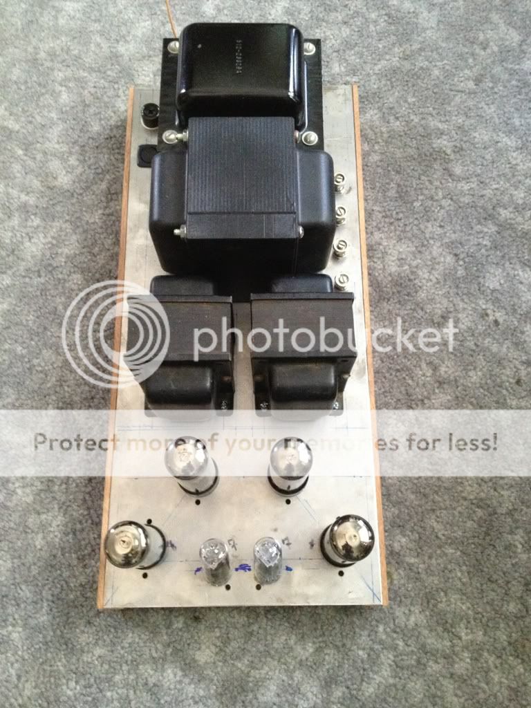
So, I decided I want to try a similar concept, but on a smaller scale. I have a pair of big Baldwin organ power transformers, and a quad of A-470 output transformers.
I'm going to parallel the secondaries, but drive both pairs from a single driver and phase inverter. The only thing I am really stumped about is how to handle the NFB. Once paralleled, there will be an 8,4, and 2ohm output.
Should I just tap off the 8 ohm to feed the feedback back into the driver stage. Will this cause any issues between the output stages, etc.?
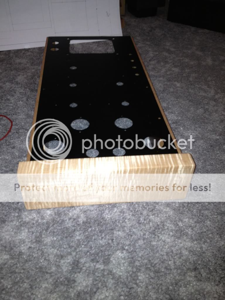
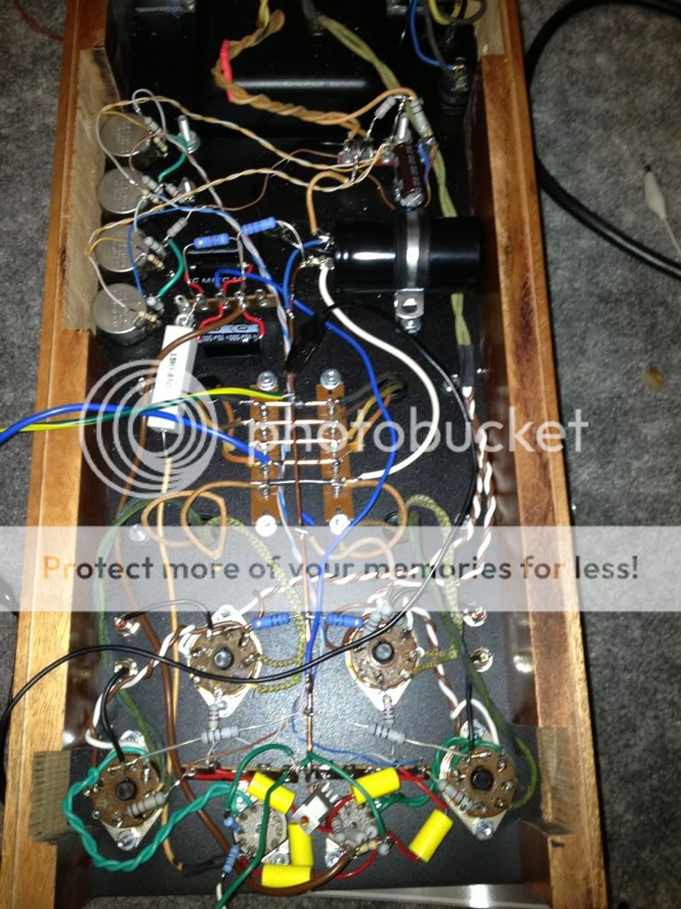
Here is one channel chassis:
So, I decided I want to try a similar concept, but on a smaller scale. I have a pair of big Baldwin organ power transformers, and a quad of A-470 output transformers.
I'm going to parallel the secondaries, but drive both pairs from a single driver and phase inverter. The only thing I am really stumped about is how to handle the NFB. Once paralleled, there will be an 8,4, and 2ohm output.
Should I just tap off the 8 ohm to feed the feedback back into the driver stage. Will this cause any issues between the output stages, etc.?
Here is one channel chassis:
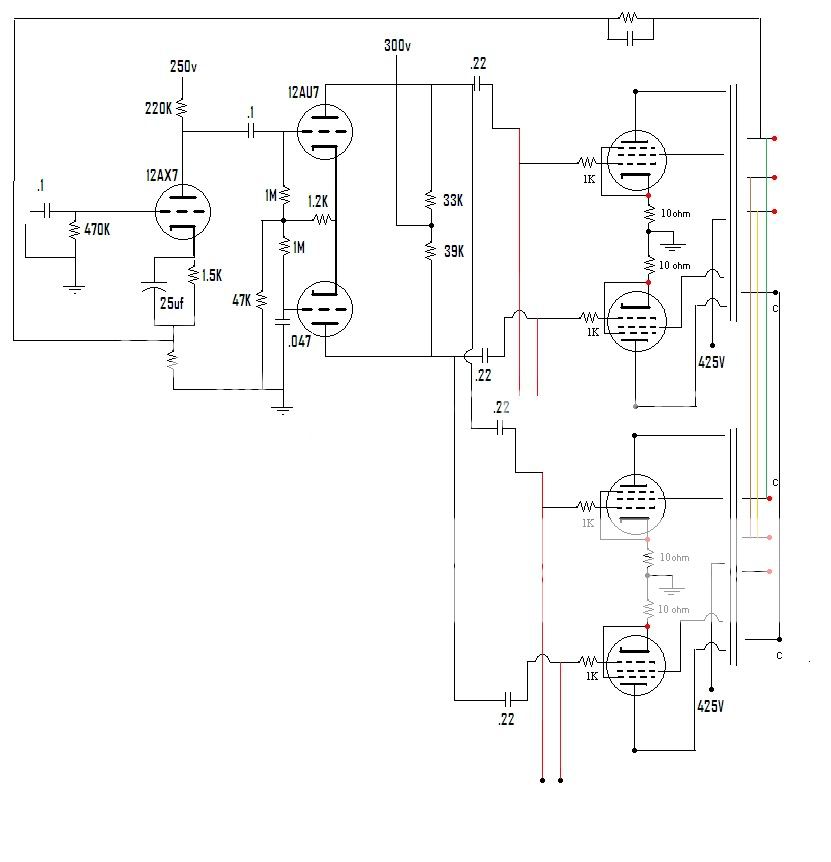
Like this? Ignore the front end. It is representative for now.
Link if that does not work:
http://i1263.photobucket.com/albums...-9543-146E31B51988-19256-00000D61EC191604.jpg
Thanks!
Blair
Since you mentioned the Bogen MO-200 I suppose you the schematic, now go find the schematic for the MO-100. Compare the feedback network for the both of them. You'll see the the paralleled MO-200 output xfmrs have either half or double the resistance and capacitance, I don't remember which. Anyway it should help you to see what's going on when parallel output xfmrs.
Craig
Craig
For feedback to work, you need "excess gain" or else your overall gain will drop kinda low... there is no requirement for gnfb (global negative feedback) or loop feedback to be used. I am not sure you have enough gain with just the 12AX7 in the front end, but that's ok.
Of course you do have gain in the second stage... getting that stage to be balanced, and the output to be balanced usually will require the use of a balance adjustment or more sophisticated means of forcing balance in the LTP...
But your question is simple to answer. If you have the secondaries in parallel then the feedback comes from the same place as if you had one single transformer. If you have the secondaries in series, then the feedback comes from the spot that is somewhere between the mid point of the two transfomers and the top end of it.
Unless, of course, you use feedback from the secondary like was done by Audio Research. Look up an early Audio Research tube amp schematic - it has been discussed here i am pretty sure.
Another option is to use lower level gnfb and use a loop feedback from the output tubes back to the LTP or farther back. Or even use a "balanced" feedback path to each tube of the LTP if you do a connection like Audio Research at the output iron...
I'd make a provision for triode strapping the outputs, I think it sounds better... watch the screen grid dissipation!
I think that 10 ohms on the cathodes makes for a bit of a "soupy" bass, but that is up to your ears to decide.
I think I recall reading that the 12AU7 is not a very linear audio tube... you might want to read up here on what people have measured for these various driver/front end tubes and maybe check that...
Btw, if you really have that B+ there, you're running the tubes pretty hard... watch the screen dissipation. I think I said that already.
Hope some of these comments might be useful...
_-_-bear
Hi Bear,
First, thanks for your commentary!
The schematic shown is representative when I was asking about how to configure the output transformer secondaries.
I started with a 6H30 VA and 6CG7 Phase Inverter. The 6H30 was nasty with oscillations and noisy as heck to boot.
I swapped it out for another 6CG7, and things are much better. I get approximately .35VAC input at 1Khz to clipping, so there is room for NFB.
I am not sure where I really want to inject it though. I am debating putting it back at the VA stage cathode like I see on traditional amplifier topologies.
I will try to draw out a final working schematic tomorrow or soon.
Regarding triode, I may do that on the faceplate with a switch.
The comment about the voltage. It is the same B+ as the Dynaco ST-70 for UL. I would never run the EL34 in triode with over 400V B+.
Thanks again!
Blair
OK,
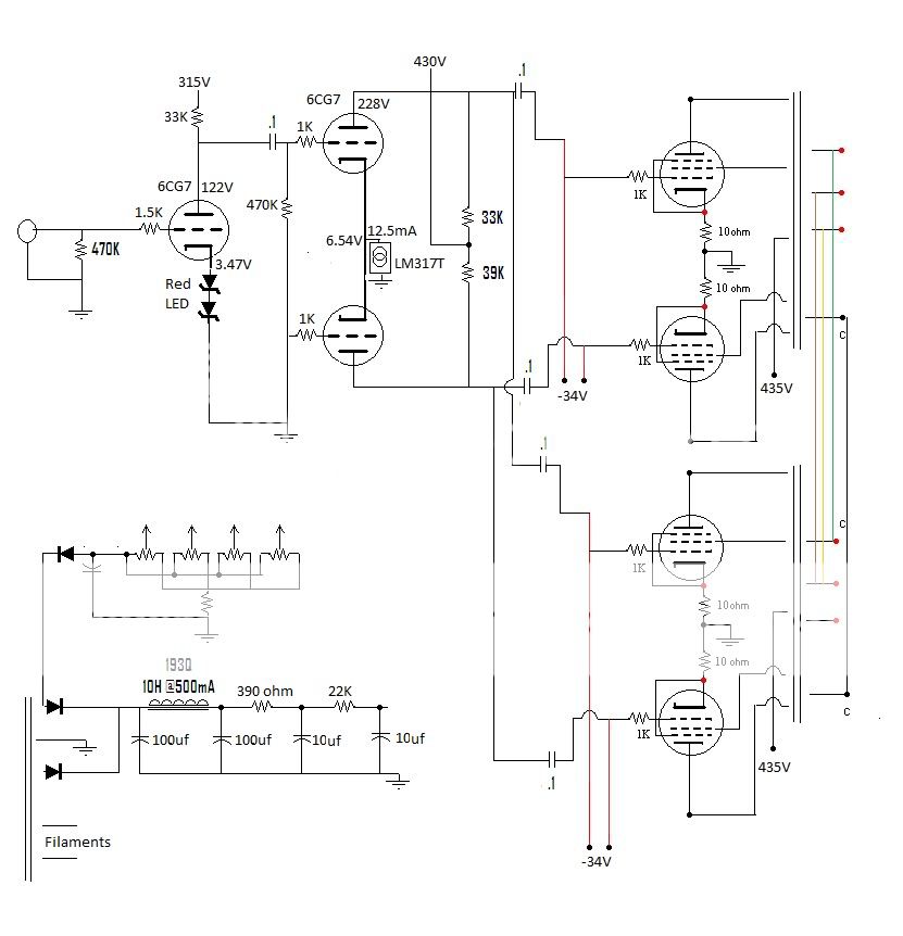
Here is an actual working schematic of what I have done:
I still do not like what the feedback does to the amp. I understand the illusion of less bass due to freq extension, but I am playing a song that has a few solid 30hz notes at the very beginning, and with no feedback, it's there. With it, it sounds extremely distorted and "out of breath". I injected it at the cathode of the VA stage before i swapped to LEDs. I'm also wondering about adding a few hundred uF of filter after the choke to "stiffen" the PS.
How do my voltages look? I just added the LED string this AM. A little more gain, but it sounds nice.
Thanks!
Blair
The feedback may be introducing LF instability, or at least an LF peak. You have 3 LF rolloffs within the loop: two coupling caps and the OPT. You need to ensure that these do not coincide, or anywhere near, otherwise you will get at the very least an LF/subsonic peak in the same region.
Thank you,
Makes sense, and the last time I used this topology or a variant, the feedback was injected at the grid of the lower triode of the phase inverter which eliminates one coupling stage. I tried both ways, and it was about the same.
The next question is, how important is Feeback? Do all amplifiers need it?
What/how would the best way to add feedback to this amplifier be? It sounds quite nice, I just want to make sure I am getting "everything" out of it.
Thanks again!
Blair
A little over my head but I'm watching. On a stock 1961 dynakit ST70 with new B+ cap and 5AR4 (stock B+ voltage) I got about 8 years out of a quad of 1970 build GE 6CA7's. Maybe 8000-10000 hours on the output tubes? I was checking output voltage into 8 ohm resistors after B+ voltage was okay each time the sound got flabby, that is how I decided to change 6CA7. The 5AR4 was changed when sound got flabby and B+ was low after new HV caps were installed. I've got a quad of matched JJ 6CA7 now on new e-caps and old 5AR4, don't know how they will last at the high voltage ultralinear, which is reputed to be hard on them.
Last edited:
The method of applying feedback is fine. It is the LF rolloffs you need to address, also the amount of feedback. Measure/calculate the 3 rolloffs. The quick and easy way to get stability is to ensure that one dominates. This may mean reducing the value of one of the coupling caps to make that rolloff dominant, or increasing them to make the OPT the dominant one. Not that this sort of issue is one reason why it is not possible to simply add or remove feedback from an amp; the right cap values for feedback may be different from those for no feedback.
The other thing besides the report of distortion is that the damping factor will get higher (lower output Z), so the nice bass might reduced by feedback depending on the Q of the speaker as it rolls off.
And no, feedback is not a requirement at all.
Check your frequency response without feedback. IF you have good iron it will be pretty flat out to 20kHz, and the iron looks big enough to handle the power, assuming enough turns on the primary then there is ample inductance for good LF response.
If you test the response up through 100kHz you will find a bump up somewhere above 10kHz, usually between ~40kHz. and 100kHz. The higher that bump, the better the HF response of the iron.
I'd bypass that LM317T with a cap... don't trust it at HF etc...
_-_-bear
Most speakers need a highish damping factor for good bass. Low damping factor with these means lots of bass, not good bass. If you want flattish frequency response with most speakers then this usually needs a lowish output Z; not enough to merely measure a flat response into a resistor.
In the second design (post 10) the 317 is the CCS in the LTP tail, so it must not be bypassed.
In the second design (post 10) the 317 is the CCS in the LTP tail, so it must not be bypassed.
") correct, it is the CCS for the LTPI.
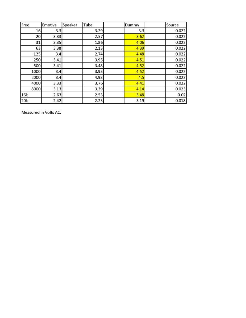
correct, it is the CCS for the LTPI. As much as it hurts my ears, I did some measurements into my speakers today. I will need aspirin, but compared to the same output voltage on my Emotiva and moving up in one octave steps, the tube amp definitely has a few rolloffs.
The iron is from the ST-70, so it should have a pretty good FR.
It would seem that testing into a dummy bank of resistors would be the most accurate for FR? The speakers have impedance profiles, and the load is reflective to the primary right? So, if my speakers are 2ohms at 20hz, but 6 ohms at 20K, then the amount of power generated is different right? Sorry for the terminology
Blair
Hi Bear,
Emotiva is my SS amplifier I used into the same load just as a benchmark of sorts.
My meter is an RMS meter. Is that what you mean?
As for the load of my speakers, they dip to about 2.5-3 ohms around 25hz.other than that, they look like an almost perfect 4 ohm load. I have the impedance profile, so that's how I know.
If you look, my source also drops output voltage where the upper end rolloff is occurring, so it is actually fairly decent like you suggest.
Blair
- Status
- This old topic is closed. If you want to reopen this topic, contact a moderator using the "Report Post" button.
- Home
- Amplifiers
- Tubes / Valves
- ST-70 mono makeover