What your measurements appear to show is a highish output impedance so voltage rises at speaker impedance peaks (16Hz (bass resonance?) and 2000Hz (crossover or tweeter resonance?)). Was this with or without feedback? My guess is without - as this lumpy frequency response into a real speaker is exactly what I would expect to see without feedback.
If you are using LED bias for the first stage then inject feedback below the LED, although above probably won't do any harm either.
If you are using LED bias for the first stage then inject feedback below the LED, although above probably won't do any harm either.
Hi,
Yes, this is without feedback. Yep, it is all easy to see looking at the impedance profile where these things occur.
If I inject below the LED, do I need to put a 100 ohm resistor between the LES and ground?
What value would you start with for a feedback resistor?
Thanks everyone for all your help!
Yes, this is without feedback. Yep, it is all easy to see looking at the impedance profile where these things occur.
If I inject below the LED, do I need to put a 100 ohm resistor between the LES and ground?
What value would you start with for a feedback resistor?
Thanks everyone for all your help!
Hi,
What value would you start with for a feedback resistor?
Thanks everyone for all your help!
Blair,
Have you determined what the gain of the amp is?
Hi 20,
At 1K with .101V input, I get 11.42VAC output. So, 113.07 is the total gain factor right?
11.42vac/.101vac= 113.07
Yep, just don't mix your scope against VOM readings. (peak vs. RMS)
I did a quicky calc from your table and came up with 225, ( 4.5/.02 ) so not sure why those numbers are so much higher.
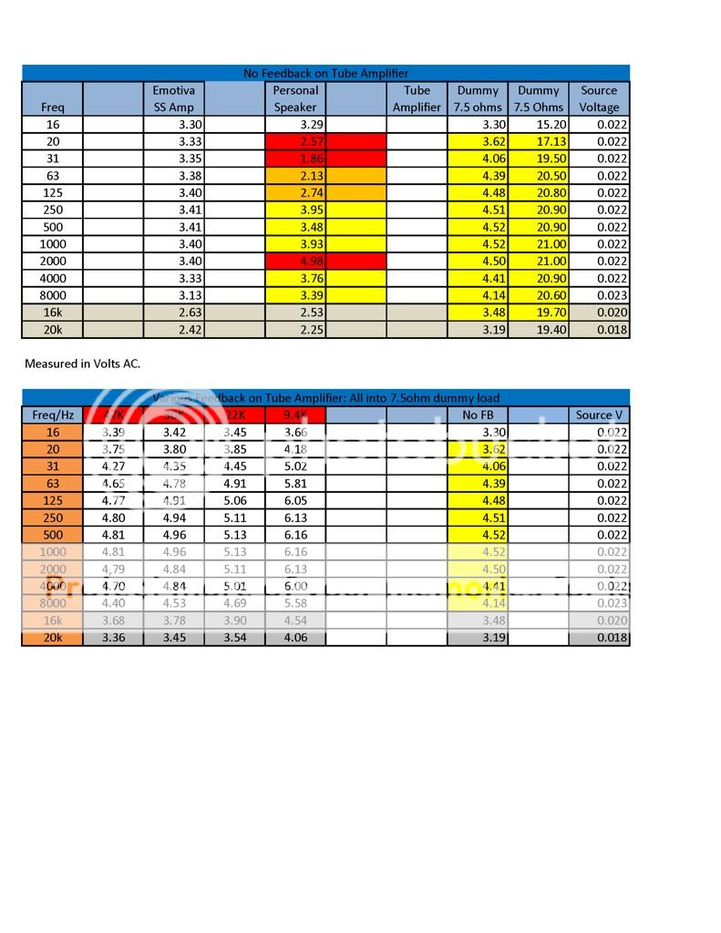
Here are the results from a few FB resistor values. Looks like 33K is the most linear to me.
I had to inject the FB between the LEDs to get it to work. Is that a no no?
The table shows your gain increases with FB. That cannot be allowed as that would be positive FB.
LED's are a gimmick. Get your amp working with conventional means first.
If you use a pot for the FB resistor you can dial down the gain to make your input sensitivity realistic and give you the output power max you want. Then set it with a fixed resistor. But remember as you change the FB resistor which is in parallel with the driver cathode resistor you will shift the biasing. So start with a slightly higher K resistor value and then add in the FB signal through the pot. If you are just stabbing different FB resistors onto the cathode you are shifting the bias point without realizing it.
Last edited:
If you simply inject feedback between the LEDs, with no series resistor, then you will need quite low feedback resistors which may load the output and you will get distortion from the LED non-linearity (small, but not negligible in this situation). You must add a resistor.
You appear to have positive feedback. Reverse the OPT secondary connections. This would explain the bad bass with feedback. The 'no feedback' lumpy response would be even worse with positive feedback.
You appear to have positive feedback. Reverse the OPT secondary connections. This would explain the bad bass with feedback. The 'no feedback' lumpy response would be even worse with positive feedback.
Yep,
No matter how I work the feedback, it is positive feedback.
I should reverse the primary connections on each power tube? Wouldn't it be easier to just move the coupling caps from the PI?
It should come from the (+) speaker connection. Whatever the signal is there "phase-wise" must be 180 degrees from he place you put it into.
Your original plan put it on the grid of the PI. What is the phase of the signal there? Your choice of phase inverter type may be why the FB seems to be positive to the driver cathode instead of it being negative there. The phase shifts through each device. It all has to add up to being 180 degrees out from where it goes back into the circuit.
If you started with a proven design, stick to it. If you just pieced it together from different topologies then you might have a wild child to tame.
Last edited:
The simplest method is usually reversing the secondary, as I said. Swapping PI coupling caps will work, but is usually a bigger change and may introduce HF problems as the stray capacitances will be different. Similarly, swapping OPT primaries can change strays. If your wiring is short and direct, as it should be, then you won't have enough slack to swap over. The secondary, being a low impedance point, is not fussy about stray capacitance.
Thanks guys!
I swapped the coupling caps at the phase inverter because it was easiest, and now I get NEGATIVE feedback")
I have a 1K cathode resistor in series with a 100 ohm to ground. 4.97V on my cathode of my CA stage. At 1K, I get .78v to full output, and I'm actually hitting my 70W before clipping.
At 15w, or 10VRMS output, the output voltage does not fluctuate more than .2V from 16Hz - 20KHz. Same for low voltage output, but I wanted to see what it does at some power.
4.7K seems to be the best value so far.
Sounds very nice as well. Now, I have to build the other one, or settle on mono.
Blair
I swapped the coupling caps at the phase inverter because it was easiest, and now I get NEGATIVE feedback
I have a 1K cathode resistor in series with a 100 ohm to ground. 4.97V on my cathode of my CA stage. At 1K, I get .78v to full output, and I'm actually hitting my 70W before clipping.
At 15w, or 10VRMS output, the output voltage does not fluctuate more than .2V from 16Hz - 20KHz. Same for low voltage output, but I wanted to see what it does at some power.
4.7K seems to be the best value so far.
Sounds very nice as well. Now, I have to build the other one, or settle on mono.
Blair
Thanks guys!
I swapped the coupling caps at the phase inverter because it was easiest, and now I get NEGATIVE feedback
I have a 1K cathode resistor in series with a 100 ohm to ground. 4.97V on my cathode of my CA stage. At 1K, I get .78v to full output, and I'm actually hitting my 70W before clipping.
At 15w, or 10VRMS output, the output voltage does not fluctuate more than .2V from 16Hz - 20KHz. Same for low voltage output, but I wanted to see what it does at some power.
4.7K seems to be the best value so far.
Sounds very nice as well. Now, I have to build the other one, or settle on mono.
Blair
You is FAST!
- Status
- This old topic is closed. If you want to reopen this topic, contact a moderator using the "Report Post" button.
- Home
- Amplifiers
- Tubes / Valves
- ST-70 mono makeover