Hello folks!
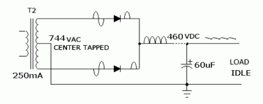
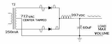
I've built an amp with 2x6l6gc P-P AB1 in the power section. There is problem that I can't solve: after full wave rectifier, B+ is 460VDC (372VAC on secondary) at idle, and 395VDC (350VAC on sec.) at full power.
Power transformer specs are: 250mA; 372-0-372VAC.
6l6 are biased (fixed bias) at 35mA each. Diodes are 1n5408 (1000v, 3A)
Well, i need more clean headroom and I can't understand why it's sagging too much . Suggestion? Tricks?
Thanks!
Attachments
Remember that transformer specs assume a resistive load. A rectifier/cap load will impose a peaky load so voltage drop will be greater.
The figures you give don't seem quite right. A 372V AC secondary should give an off-load DC of around 520V, but you are getting about 10% less. It may be that the AC waveform has the peaks flattened so the ratio between peak and RMS is not the 1.414 for a pure sine wave. Take the 350VAC under load, knock off 10% then multiply by 1.4 to get 441V. If the DC current is 200mA then the ripple will be about 33V so we are down to 408V.
It is a feature of power supplies that they usually droop more than expected.
I'm guessing the sag is caused by the increased supply ripple. I suggest increasing the reservoir cap. A quick calculation estimates the ripple voltage to be about 40 V at max load; 5.8 V at idle. Increasing the reservoir cap to, say, 470 uF would give you 5.3 V ripple at full load...
For a better understanding, I suggest running a sim in LTspice or PSUD II.
From physics: C = Q/V; Q = i*t --> V = (i*t)/C; t = 1/(2*f) for a full-wave rectifier. --> V = i/(C*2f)
C = capacitance in Farad; Q = charge in Coulomb; V = peak-peak ripple voltage in Volt; t = time in seconds; f = line frequency in Hertz; i = load current in Ampere.
Above calculation assumes zero resistive losses, neglects the diode forward drop, and assumes a zero conduction angle. So take it as a worst case ripple estimate. For a more exact value, run a sim.
~Tom
Last edited:
Sag is not on secondary winding (only few volts), but after the diodes/filter cap.
That is exactly what you would expect if the reservoir cap is too small.
It's quite commonly used in guitar amps where some designers use that on purpose to create PS sag.
What is coming after the first cap? Choke or resistor?
I can't imagine this is directly connecting to the OPT center tap?!?
Try to sim it in PSUDII once you know the winding resistance of the PT (as tomchr suggested), it's an eye-opener.
Cheers,
Martin
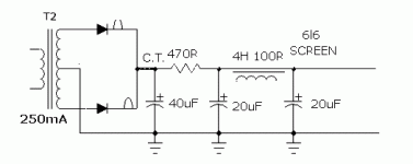
Today I improved the voltage drop and sagging (~410vdc @ max volume) decreasing first cap value (down to 40uF) and adding a 470R resistor between first cap and choke. I've tried to increase the first cap value, but the sagging was too much. Heres the schematic:
Attachments
Your 1000V diodes are not quite sufficient. You have a 744 VAC transformer, so the the peak voltage (per side) is 1052V! Don't forget that during the other half of the AC cycle, the voltage on the diode anode will swing to the negative side. Opposed to the positive voltage on the cap (and cathode), you are approaching and likely exceeding the 1000V breakdown voltage. And that's without accounting for component tolerances, slightly hot line voltage, etc. It is possible that the diodes are at least partly conducting in reverse and taking some charge out of the cap. Try to find something with higher breakdown voltage.
Last edited:
How about the DCR of your choke?
100 ohm
A pair of 6L6GC powered at 450V and loaded with 5600 ohms can deliver some 50W and draws 230mA from the B+ to do that.
With such HI DCR values for the transformer and the choke, (150 + 100 that is 250 ohms) a minimum of 57V of B+ drop is . . . normal
Enter thoose values in PSUD and check yourself.
Yves.
With such HI DCR values for the transformer and the choke, (150 + 100 that is 250 ohms) a minimum of 57V of B+ drop is . . . normal
Enter thoose values in PSUD and check yourself.
Yves.
I guess I am a little confused on your design. The first picture only shows the transformer, diodes and one capacitor. The second shows more, but now has an extra CR filter in front. With a transformer DCR of 150, choke DCR of 100, AND an additional 470R in the way, you have a mess.
Start over, model it in PSUD. Start with a more standard CLC plan and model the load as a current sink. Make sure you input the correct values for your iron, and play with it until you get reasonable results and make sure components like the diodes and capacitors can handle the large voltage swings.
Start over, model it in PSUD. Start with a more standard CLC plan and model the load as a current sink. Make sure you input the correct values for your iron, and play with it until you get reasonable results and make sure components like the diodes and capacitors can handle the large voltage swings.
- Status
- This old topic is closed. If you want to reopen this topic, contact a moderator using the "Report Post" button.
- Home
- Amplifiers
- Tubes / Valves
- Big B+ voltage drop using diode rectifier.


