Just look at the site can not find any 13lr8 anyware ?not the 6lr8, but the 13lr8 is...at rogalski's in florida...
they have 21lr8 for 1 dollar so I guess he meant 31lr8 .21lr8, 31lr8 ... no 13lr8
not sure they exist
no 13lr8 not sure they exist
I don't think they do. The odd voltage tubes were created to operate with all the heaters wired in series operating from line voltage. They all must have the same current rating for this to work. The common series current ratings for TV sets are 300 mA, 450 mA, and 600 mA.
The 300 mA tube is the 31LR8 (31.5 volts)
The 450 mA tube is the 21LR8 (21 volts)
The 600 mA tube is the 16LR8 (15.8 volts)
And the 6LR8 is a parallel 6.3 volt tube at 1.5 amps.
These all consume 9.45 watts of heater power. If there was a 13LR8 it would run at a very non standard 725 mA.
The 31LR8 and the 21LR8 were on the 75 cent list until Dales inventory got back to "normal" levels, then they were removed. I am responsible for the 6HB6 being removed from the list. The 6LU8 was indeed $2 at VacuumTubes.net some time in the past. I make spreadsheets of cheap tubes VS applications, and I have an old one listing the 6LU8.
The 16LU8 and 21LU8 (12 pin version) and the 31LR8 are still on the dollar list at ESRC.
With the schematic that vinylkid posted here. What might be a good substitute for the 5V4GA rectifier? My AC input would be ~ 355vac. I have on hand a 5R4GY (which I can't make heads or tales of the spec sheet, it seems to have more info on operational allitude, it is a JAN tube so I guess it belongs in a B-27 bomber), 5U4GB (from what I can tell wouldn't be as much voltage output as the 5V4GA), GZ34 (which doesn't appear to put out as much as the 5V4GA), and a 5Y3 (which I'm fairly sure won't do) Any suggestions?
He asked for rectifier subs?
simply try what you have and see what it brings (after you have checked the specs)
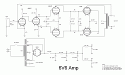
I've decided to go with this design. Any suggestions on improvements?
![IMGDEAD]](https://www.diyaudio.com/forums/[IMGDEAD]http://i263.photobucket.com/albums/ii151/cameramanlink/6V6StereoAmp-1.gif[/IMGDEAD])
![IMGDEAD]](https://www.diyaudio.com/forums/[IMGDEAD]http://i263.photobucket.com/albums/ii151/cameramanlink/6V6StereoAmp-1.gif[/IMGDEAD])
An externally hosted image should be here but it was not working when we last tested it.
Last edited:
This is essentially the Williamson circuit which has way more gain than required for use with the 6V6 even with pretty significant levels of global feedback applied. It also frequently exhibits LF instability that is almost impossible to eliminate if you do not have profound understanding of loop stability criteria and the equipment required to measure the open loop phase shift and gain.. (Think Bode plot here)
A variation of the Mullard 5-20 circuit with a high mu triode like the 6SL7 in the front end might be a better (sounding) choice. Gain while still high may be made more in keeping with modern sources like CD players and DACs..
A variation of the Mullard 5-20 circuit with a high mu triode like the 6SL7 in the front end might be a better (sounding) choice. Gain while still high may be made more in keeping with modern sources like CD players and DACs..
I've decided to go with this design.
Why?
Any suggestions on improvements?
Needlessly complex with a mediocre power supply. You're building a "mono" amp right, not a pair of mono-blocks for stereo? I like the schem. I posted earlier way better, I'd just change the PS a little.
jeff
vinylkid, Actually this will be a pair of mono-blocks. I could tell the ps was weak and was looking into beefier alternatives. I like the schem you showed earlier, but was put off by the filter chokes. I'm trying to build this with parts on hand. Kind of a garage junk build with a sound of gold  . And it doesn't look complex, compared to a couple other designs I've built it actually looked fairly simple.
- Status
- This old topic is closed. If you want to reopen this topic, contact a moderator using the "Report Post" button.
- Home
- Amplifiers
- Tubes / Valves
- 6AU6 replacement
