I've been lurking this forum for quite a while now and have made 2 amps from designs I picked up here. They all worked perfectly so I decided to try to make my own. I'm an electrical engineering student so I thought I could tackle the task. I've spent the past few months designing and constructing this amp but last week I turned it on to find that I completely failed.
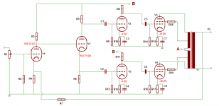
This is a stereo, monoblock PP KT88 Class A amp. I've spent the last week trying to figure out what's wrong with it but I cannot, for the life of me, find anything that fixes the problems. Please, if someone here could take a bit of time and maybe there's something that I'm overlooking by lack of experience that you could let me know?
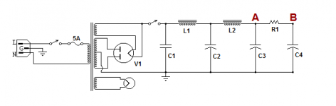
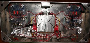
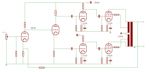
I'm attaching the full schematics as well as pictures of my actual circuitry.
The list of problems:
- Right channel is reproducing music veeery quietly.
- Left channel had an awful loud distortion/hum (no music playing and even when the potentiometer was off). This went away just by moving wires near the power supply, but still no music playing.
- Measurements of my B+ are somewhat close on my right channel, but fluctuate heavily on the left one. When I could hear the noise I was getting 410 [V] right after the stand-by switch. After moving wires and no hum, it's at 565 [V].
- If I move the potentiometer my power supply voltage increases
Thank you very much in advance to anyone who could take to try to help me out.
This is a stereo, monoblock PP KT88 Class A amp. I've spent the last week trying to figure out what's wrong with it but I cannot, for the life of me, find anything that fixes the problems. Please, if someone here could take a bit of time and maybe there's something that I'm overlooking by lack of experience that you could let me know?
I'm attaching the full schematics as well as pictures of my actual circuitry.
The list of problems:
- Right channel is reproducing music veeery quietly.
- Left channel had an awful loud distortion/hum (no music playing and even when the potentiometer was off). This went away just by moving wires near the power supply, but still no music playing.
- Measurements of my B+ are somewhat close on my right channel, but fluctuate heavily on the left one. When I could hear the noise I was getting 410 [V] right after the stand-by switch. After moving wires and no hum, it's at 565 [V].
- If I move the potentiometer my power supply voltage increases
Thank you very much in advance to anyone who could take to try to help me out.
Attachments
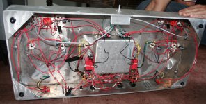
Just a couple of suggestions. The wiring is a bit of a rat's nest. Have a look at some other amps that have been worked on by others here for examples of neat wiring. Also, using different colours will help indentify errors. I would fit "Grid Stopper" resistors (eg 4k7) to each control grid close to the valve base to stop any odd oscillations. Also, temporarily remove R7 to remove the feedback ( in case its positive instead of negative). One more thing, try removing the coupling caps to see if each stage is stable on its own.
Use solder more, screws less. Try to get away from flying connections. Get some terminal strips 5-Position Terminal Strip : Terminal Strips | RadioShack.com
Keep components close to each other; like where the preamp is, the only wires going to it would be the audio in, ground (from your one signal star ground), B+, feedback, and audio out. All components should be directly connected. The power amp tubes should be close to the output transformers, with just an audio in wire, ground, anode to transformer, screen to transformer.
Is one hella chassis.
Would be much easier with the component values on the schematic.
It would be 30 volts on the cathode, instead of -30? With 30 volts across a 150 ohm resistor that would be 200ma through the KT88, or about 80 watts?
Last edited:
Here's one with too perfect wiring. You don't want the signal wires compressed together, with each other or B+, except if they are all the same level (like all audio inuts). Other than that, his builds are excellent. And you'd rather have filament wires, even when twisted to run perpendicular to signal wires. Morgan Jones' Valve Amplifiers 4th edition would make for some excellent reading.
Well Come My WebSite Audio Collections
Well Come My WebSite Audio Collections
Yes. Did you get a good deal on red wire?payitforwardeddie said:Also, using different colours will help indentify errors.
DeathRex: Yeah, I've been using Morgan Jones' Valve Amplifiers almost as a Bible haha.
DF96: Yup! I bought a 100ft spool, but I don't know if its too thick... Soldering 16 awg wasn't easy.
I'll try to re-do all the wiring... I think this is kinda good news, I was worried someone might look at the schematic and say that I made a mistake on my circuit design (meaning a more expensive fix)...
Thanks for the responses! If ya'll got any more advice/tips/comments I'd appreciate it!
dgta: I'll do that!
I noticed my heaters' center tab wasn't grounded, so I did, but the problem isn't gone. Two things are happening right now:
-One channel has a crazy loud hum (even if the pot is at off). If I turn the pot, the hum changes.
-I'm getting the right B+ now but when I turn the pot for more volume (even without music playing), that voltage goes higher. Is this normal?
See my previous post.
As an EE student, you should know by now that you need to go about this in an orderly, organized manner. Don't jump around trying this and that at random. Start by measuring all DC voltages at quiescent (shorted input). Post that and fix all obvious discrepancies.
Once that's done, connect a signal and make sure there is no DC on that signal source. Then measure AC signals down the line. Again, faults will be obvious.
Hi,
I'm still pretty new at this too, so no doubt someone will correct me, but in your schematic your phase splitter (2nd half of V1) has no grid leak resistor, so the grid is just floating?? (has no ground reference)... I would imagine this would lead to some pretty funky effects... maybe try a 1M or 500K resistor from the grid to the top of R6?
cheers,
Jacob
DeathRex: Yeah, I've been using Morgan Jones' Valve Amplifiers almost as a Bible haha.
Building Valve Amplifiers, by the same author, should also be in your library, very good reference for construction
Jacob, the Phase Inverter gets DC reference directly from the previous stage (so it is fixed biased), so no use for a grid leak. It does still need a grid stopper though...
Last edited:
aardvarkash10: The actual grounding is not like the schematic, I have everything running to one main star ground near the back and center of the chassis, I thought that would eliminate ground loops.
jazz: Yeah, shortly after posting the picture I noticed my KT88 caps kept coming off.
DeathRex: You were right! The resistor values for my cathode bias are wrong, I used the equivalent resistance seeing by the caps (used to calculate the cap value) instead of the correct cathode resistance. I've already ordered those new resistors.
dgta: Because of the resistor thing, I'm going to wait until I get those DC values since some of the component values are wrong.
There is one channel that is actually reproducing music, however the bias for my KT88s on that channel is 55 [V] and 48 [V]. The music is not very loud and a bit distorted.
The other channel still has that LOUD, low frequency hum. I've tried disconnecting coupling capacitors going from the output towards the input. I've found that if I disconnect the input to the KT88s, the hum is gone. If I disconnect the input to my driver after the phase splitter, the hum is gone. If I disconnecting my input from the pot to the pre-amp before the phase splitter, the hum is there. So this hum seems to be originating between my pre-amp and phase splitter.
I rewired that entire section and the hum is still there....
Hi EE,
I have a pair of push pull kt 88 monoblocks. Your assertion above is correct. The thing to do now is try using the non humming channels front end to drive signal to the phase splitter on the humming side to assert that it is the pre at fault, and then try to figure out the difference between them. Use screened wire, seeing as how you will be linking over lots of circuit that can add hum. I am sure you will have a bad connection somewhere- it is very easy to do when you use the same colour cable everywhere- I have rectified a few diy'ers errors (and others who ought to know better) due to this.
I have a pair of push pull kt 88 monoblocks. Your assertion above is correct. The thing to do now is try using the non humming channels front end to drive signal to the phase splitter on the humming side to assert that it is the pre at fault, and then try to figure out the difference between them. Use screened wire, seeing as how you will be linking over lots of circuit that can add hum. I am sure you will have a bad connection somewhere- it is very easy to do when you use the same colour cable everywhere- I have rectified a few diy'ers errors (and others who ought to know better) due to this.
Hi EE,
one problem at a time. Try to eliminate the source of the hum first.
Then check all your cathode bias resistors and caps, and the pinout of your kt88s.
It sounds like one amp has a good balanced output. Check to see if both amps cathode resistors correspond, and then try to swap valves and see if the values match.
Between both amps it sounds like you have at least one working amp. Should be easy to add them together and then cross reference to get both running.
Good luck.
Before I have to run off I would like to say that construction techniques are important.
orientate tube sockets so the heater windings and leads are away from signal lines.
keep the parts mechanically stable by putting them between terminal strips then wire to the socket.
and also briefly looking at the schematics stay away from cathode bias unless you want to tweak the design to offset the uneven signal loading and amplitudes. use fixed bias method like a -40V supply adjustible type through 100k-220k resistors. like this:
So, I took the main advice and completely re-did the wiring, the only ones I didn't de-solder and re-soldered are in the power supply (middle section), the rectifier tubes and some heaters.
Also, I made DC measurements at several points for both left and right channel.
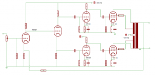
I have attached all this info on the post. (Original post has the component list and circuit diagram with the calculated values)
After re-doing the wiring and changing the resistor values for all cathode bias (turns out I had the wrong values). THE PROBLEM IS STILL THERE!
Left channel has CRAZY LOUD HUM.
Right channel dead quiet. Also before changing the wiring I unplugged the humming side and the right side did play music but it was a bit quiet and distorted.
Anyone has any advice? I thought for sure changing the connections would fix it, now I'm wondering if I have a busted tube or even OPT?
Thanks again to everyone who's taking time to help out.
Also, I made DC measurements at several points for both left and right channel.
I have attached all this info on the post. (Original post has the component list and circuit diagram with the calculated values)
After re-doing the wiring and changing the resistor values for all cathode bias (turns out I had the wrong values). THE PROBLEM IS STILL THERE!
Left channel has CRAZY LOUD HUM.
Right channel dead quiet. Also before changing the wiring I unplugged the humming side and the right side did play music but it was a bit quiet and distorted.
Anyone has any advice? I thought for sure changing the connections would fix it, now I'm wondering if I have a busted tube or even OPT?
Thanks again to everyone who's taking time to help out.
Attachments
- Status
- This old topic is closed. If you want to reopen this topic, contact a moderator using the "Report Post" button.
- Home
- Amplifiers
- Tubes / Valves
- PP KT88, Need help!