Hi I am fairly new to the forum and about to start my first little project which should keep me busy for around a month.
I have purchased a pair of Quad 2 Amps, I decided to go for a pair that needed restoration as at least I will know whats inside them rather than buy suposidly workign ones only to find they need lots of replacement parts inside anyway.
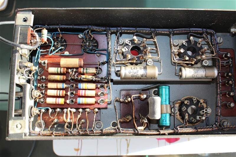
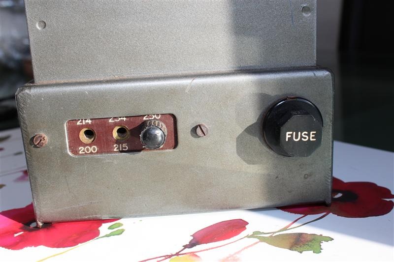
So I decided to start on them this morning, first thing I did was take a lot of detailed picture of them so I could see what they looked like when they were together.
My 2 amps are not that close in serial numbers and I understand that this does not matter, but I will be wanting to test this and make sure they perform within QUAD's specification.
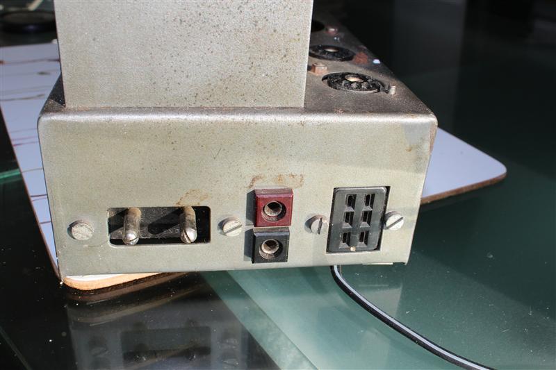
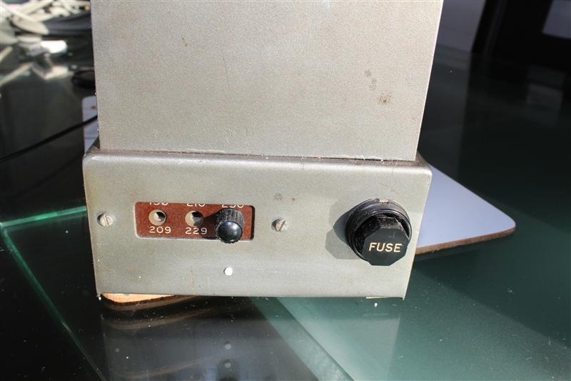
I will not be restoring these 100% original, I will be including a few safer features like chassis earth, and some better plugs and sockets on the exterior, I would also like to move all connections to the rear so I havnt got cables coming in from the front and back.
Anyway to start the post off here are some pics of what I have now:
Amp 1:
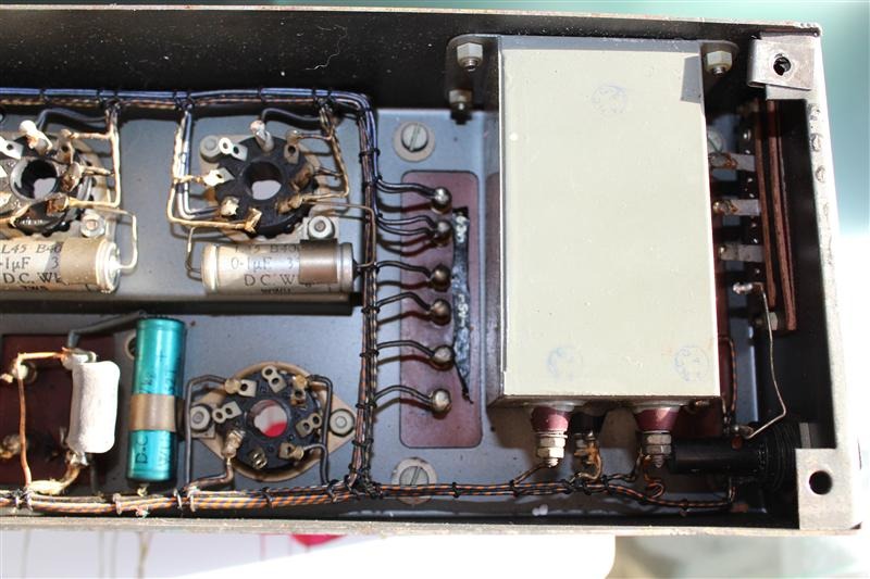
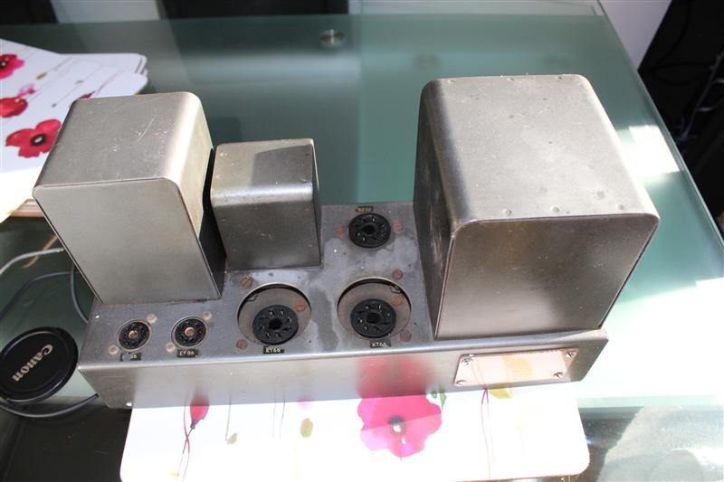
Amp 2
I have purchased a pair of Quad 2 Amps, I decided to go for a pair that needed restoration as at least I will know whats inside them rather than buy suposidly workign ones only to find they need lots of replacement parts inside anyway.
So I decided to start on them this morning, first thing I did was take a lot of detailed picture of them so I could see what they looked like when they were together.
My 2 amps are not that close in serial numbers and I understand that this does not matter, but I will be wanting to test this and make sure they perform within QUAD's specification.
I will not be restoring these 100% original, I will be including a few safer features like chassis earth, and some better plugs and sockets on the exterior, I would also like to move all connections to the rear so I havnt got cables coming in from the front and back.
Anyway to start the post off here are some pics of what I have now:
Amp 1:
Amp 2
It's a long time since I had Quads - believe it or not I once bought a job lot of 26 with line outputs that came from a factory. Yes, they're all sold long ago..... Quad in Huntingdon were rather bemused at a request for 26 output transformers but they did provide them.
I agree with updating the connections. You'll want better resistors - I'm sure the tweakers can advise. But keep all the old parts and remove them carefully in case you sell one day to a collector, so you could include them in the sale. The first thing I'd do is buy 6 Russian FT-3 teflon caps to replace the 0.1 caps. These teflon caps are superb - ultra clean and detailed. They are bigger, so will need to be elevated in some way. I'm assuming they will fit somehow or somewhere! I use a lot of hexagonal nylon spacers, male-female M3 with a solder tag and nyloc nut (important to stay tight when you solder). You can mount these instead of nuts on M3 bolts in existing holes, for example the bolts holding in the tube sockets. And you can stack them so you get a few solder tags on one pillar. Very useful for discreet mods of old equipment.
There are many better input sections you could use, but that's for a later day when you have cleaned up all the parts that need it.
Last edited:
Hi Andy thanks for the reply ")
I was going to replace all resistors with 3W Metal film except the R12 whichI was going to use a 5W for as I had read this one gets hot and had already been replaced with a much larger one in Amp 2.
Funny you mentioned the Russian capacitors, I didnt know about them ones but had already ordered the K40Y variant which I think are god quality around the same size and look of the originals and still metal screened. Do you think they would be a lot to be gained between the 2?
Anyway I have stripped Amp 2 down to the metal work today and will build this one up first, still wondering if I like the original grey paint, and if I do what the closest match would be, mine are both original and look a bit like grey hammerite paint but with smaller 'hammer' effect. I do quite like the idea of doign them in the latest colours for some reason, so they would look like the modern classic 2 - so choice is Original | Modern | somthing very shiney so the glow refects off them in the dark.
Hi Andy thanks for the reply
I was going to replace all resistors with 3W Metal film except the R12 whichI was going to use a 5W for as I had read this one gets hot and had already been replaced with a much larger one in Amp 2.
Funny you mentioned the Russian capacitors, I didnt know about them ones but had already ordered the K40Y variant which I think are god quality around the same size and look of the originals and still metal screened. Do you think they would be a lot to be gained between the 2?
Resistors that get hot should be rated at twice the wattage or even more for comfort. Look at the Welwyn green porcelain wirewound ones. If a 14W fits, you could use that (W24) or otherwise a 10W (W23) or 7W (W22)
There's a world of difference between K40 which is PIO and K72 and FT-3 which are teflon. The FT-3 are ever so slightly better than the K72, but the main thing is they are slightly smaller. Some people find the teflon "sterile" and prefer PIO K40s, but frankly I think they are much inferior. Teflon is the ultimate in clean and detailed. I don't get all this "warm sound is nice" stuff.
I found the biggest improvment was some big pp supply smoothing caps. tightens the bass no end, but it doesnt sound like a quad then!
having bulit a few amps of my own design now, i'm full of admiration for quad in getting a valve rectified push pull amp into such a small chassis.
enzo
having bulit a few amps of my own design now, i'm full of admiration for quad in getting a valve rectified push pull amp into such a small chassis.
enzo
I found the biggest improvment was some big pp supply smoothing caps. tightens the bass no end, but it doesnt sound like a quad then!
having bulit a few amps of my own design now, i'm full of admiration for quad in getting a valve rectified push pull amp into such a small chassis.
enzo
Hi Enzo, when you say big what values are we talking about ?
I was considering moving from 16 to 47 or maybe 68uF.
There's a world of difference between K40 which is PIO and K72 and FT-3 which are teflon.
I will purchase some FT-3's and see if I can get them in there nicely, worst case is they will sit and wait for somthing else.
oh boy , what a treat of a project
whatever - regarding first cap after tube rectifier - stay as low as possible , it will increase rectifier longevity
if you want tighter bass ( in fact - amp faster overall ) - put RC after first C , so that second C can be bigger
I think 47R to 68R/5W will suffice , without sacrificing too much of Ub
150mA x 47R will give ~ 7V of drop
Mmmm .....
I should stay away - but ever since I heard the first Quad II down here south in 1956 (with EL loudspeaker) and befriended Peter Walker, this little engineering marvel got close to my heart. If I may then advise (kindly excuse the length):
I could start with the dozens I have refurbished thus far, but let us leave the 'promotion' there. Firstly, my respects to those promoting super-caps .... but in audio there is no reason not to use normal polyester or polyprop. capacitors for coupling. Yes, there are far better caps out there (at a price, naturally), but define 'better'. Those are made for medical purposes or measuring instruments where the 'betterness' is of value - not here*
Also, I feel you are overdoing things with 3W resistors. For most of them 0,25W MF is ample, but they look rather silly small. I replace with 0,5W or 0,6W MF where obtainable. If you like the 'same size' look of 1W MFs better, fine - but no technical requirement for such.
I usually make R12 10W, but then rather to distribute heat more than necessity. Anyway, keep in mind that component ratings are usually for 25 degrees ambient; it is higher underneath a Quad chassis.
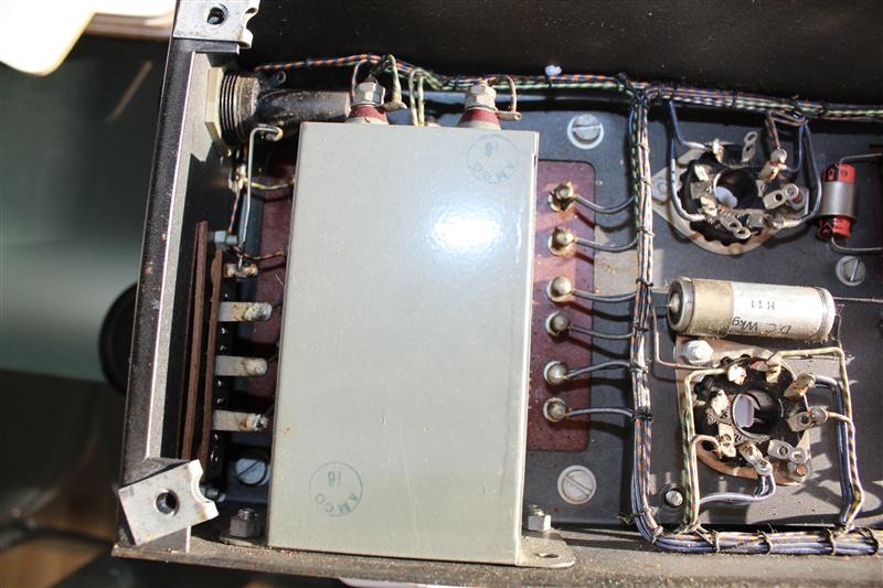
If desired by the owner I remove C4 and C6 from the tin - there is a twin can capacitor inside. One can unsolder the bottom with a gas flame and do a neat job of it. Regarding values, using a GZ34 rectifier as all later Quads did, the filter input capacitor may be 60µF maximum. Modern types are quite small in size, and C6 = 47µF and C4= 100µF, both 450V, can fit in quite comfortably. I use some polyurethane foam inside to keep the caps from dangling around and the can lid is easy to replace. A re-paint job might be needed.
C5 is the one other component I change - quite drastically. Though the class-A design is supposed to draw constant current, there is a small rise in KT66 current at full output thus back-biasing. The effect of fixed bias is simulated for music by making C5 quite large. I use 2200µF 35V or at least 1000µF 50V, whatever is available. Again small physical size these days. Up to 20W of peak output is possible this way.
And Clintek! Please keep the hot R12 away from right next to C5! It is the only stupid thing I ever saw Peter Walker do. Heat is the enemy of especially electrolytic capacitors! I have not had a single Quad II where C5 was not completely dried out. One can glue C5 to the chassis just next to V5, but move R12 away to the component side, mounted somewhat higher on its leads.
Semiconductor rectifiers are attractive, but somehow a Quad with an empty valve socket does not appeal. Some leave the valve in non-operative .... There is the slight advantage of a tube rectifier bringing in a soft start.
Then, the equal voltages showed on the electrodes of the EF86s are incorrect; they cannot be equal as V2 takes its G1 potential from a slightly positive point in the circuit, thus making V2 potentials about 15% lower than those for V1.
Replacing C2, C3 by capacitors without the outer earthed metal body removes about 22pF from KT66 grids to common. As a result you will find a slight overshoot at about 100kHz on the output looking at a square wave. One can restore by placing external 22pFs there, but I prefer a phase lead correction. This is accomplished by the addition of a 1500nF capacitor in parallel with R11. Not really essential, but just to make matters neat ....
Finally! One finds shape resembling KT66s these days, but at a cost. Otherwise keep the following in mind. The 6L6GC equals the KT66 to about 10% (this is < than the tolerance on tube production). It draws lower heater current but is rated at 30W compared to 25W for a quite more expensive KT66. (You will find that some Russian KT66s have the exact same innards as 6L6GC - at higher cost!) And please keep EL34s out of the mix! They are quite different from the KT66 and draws more heater current.
Thanks for your patience.
*I am always puzzled by the paranoia regarding quality of coupling caps. Yes, of course they must not leak; hardly a concern these days. But consider all the talk about dielectric absorbtion, smearing and what else .... These capacitors are shorts at all audio frequencies, they do not charge/discharge except initially; those 'shortcomings' if of meaning are not operational during signal passing. Just thought I would mention in passing. Don't waste your money on boutique-ism.
I should stay away - but ever since I heard the first Quad II down here south in 1956 (with EL loudspeaker) and befriended Peter Walker, this little engineering marvel got close to my heart. If I may then advise (kindly excuse the length):
I could start with the dozens I have refurbished thus far, but let us leave the 'promotion' there. Firstly, my respects to those promoting super-caps .... but in audio there is no reason not to use normal polyester or polyprop. capacitors for coupling. Yes, there are far better caps out there (at a price, naturally), but define 'better'. Those are made for medical purposes or measuring instruments where the 'betterness' is of value - not here*
Also, I feel you are overdoing things with 3W resistors. For most of them 0,25W MF is ample, but they look rather silly small. I replace with 0,5W or 0,6W MF where obtainable. If you like the 'same size' look of 1W MFs better, fine - but no technical requirement for such.
I usually make R12 10W, but then rather to distribute heat more than necessity. Anyway, keep in mind that component ratings are usually for 25 degrees ambient; it is higher underneath a Quad chassis.
If desired by the owner I remove C4 and C6 from the tin - there is a twin can capacitor inside. One can unsolder the bottom with a gas flame and do a neat job of it. Regarding values, using a GZ34 rectifier as all later Quads did, the filter input capacitor may be 60µF maximum. Modern types are quite small in size, and C6 = 47µF and C4= 100µF, both 450V, can fit in quite comfortably. I use some polyurethane foam inside to keep the caps from dangling around and the can lid is easy to replace. A re-paint job might be needed.
C5 is the one other component I change - quite drastically. Though the class-A design is supposed to draw constant current, there is a small rise in KT66 current at full output thus back-biasing. The effect of fixed bias is simulated for music by making C5 quite large. I use 2200µF 35V or at least 1000µF 50V, whatever is available. Again small physical size these days. Up to 20W of peak output is possible this way.
And Clintek! Please keep the hot R12 away from right next to C5! It is the only stupid thing I ever saw Peter Walker do. Heat is the enemy of especially electrolytic capacitors! I have not had a single Quad II where C5 was not completely dried out. One can glue C5 to the chassis just next to V5, but move R12 away to the component side, mounted somewhat higher on its leads.
Semiconductor rectifiers are attractive, but somehow a Quad with an empty valve socket does not appeal. Some leave the valve in non-operative .... There is the slight advantage of a tube rectifier bringing in a soft start.
Then, the equal voltages showed on the electrodes of the EF86s are incorrect; they cannot be equal as V2 takes its G1 potential from a slightly positive point in the circuit, thus making V2 potentials about 15% lower than those for V1.
Replacing C2, C3 by capacitors without the outer earthed metal body removes about 22pF from KT66 grids to common. As a result you will find a slight overshoot at about 100kHz on the output looking at a square wave. One can restore by placing external 22pFs there, but I prefer a phase lead correction. This is accomplished by the addition of a 1500nF capacitor in parallel with R11. Not really essential, but just to make matters neat ....
Finally! One finds shape resembling KT66s these days, but at a cost. Otherwise keep the following in mind. The 6L6GC equals the KT66 to about 10% (this is < than the tolerance on tube production). It draws lower heater current but is rated at 30W compared to 25W for a quite more expensive KT66. (You will find that some Russian KT66s have the exact same innards as 6L6GC - at higher cost!) And please keep EL34s out of the mix! They are quite different from the KT66 and draws more heater current.
Thanks for your patience.
*I am always puzzled by the paranoia regarding quality of coupling caps. Yes, of course they must not leak; hardly a concern these days. But consider all the talk about dielectric absorbtion, smearing and what else .... These capacitors are shorts at all audio frequencies, they do not charge/discharge except initially; those 'shortcomings' if of meaning are not operational during signal passing. Just thought I would mention in passing. Don't waste your money on boutique-ism.
Last edited:
Hi Andy thanks for the reply
..... but had already ordered the K40Y variant which I think are god quality around the same size and look
Me again.
Jeepers Clintek, I did not notice that. I must agree with Andy. There is an unrealistic degree of snake-oil attached to paper-in-oil. Materials have developed tremendously over the last decades, no need for that technology any more. And if they are so-called NOS .... no-no. Old materials age regardless.
But OK - not to discourage you. If ordered its done, but see my previous notes.
Johan clearly knows his stuff with Quads. My only disagreement is that coupling caps ARE audible and do matter. Polyester? No thanks. Polyproplene? Better but no cigar. The Teflon FT-3s are superb caps. They are not leaky boutique PIOs (plenty of threads about Jensen etc.). They are military quality teflon. I've used many and done endless cap shootouts and they are my clear choice.
As for caps in the PSU, if you can make the last cap polypropylene that would be good, but depends if you have the space.
As for caps in the PSU, if you can make the last cap polypropylene that would be good, but depends if you have the space.
Johan already explained how the coupling cap cannot be audible.
What's your explanation to the opposite? You did a shoot out? What does that prove exactly?
Not trying to be mean, I just don't see your point of view. A "shoot out" is fueled entirely by expectancy bias, which renders the whole thing completely invalid.
What's your explanation to the opposite? You did a shoot out? What does that prove exactly?
Not trying to be mean, I just don't see your point of view. A "shoot out" is fueled entirely by expectancy bias, which renders the whole thing completely invalid.
Johan already explained how the coupling cap cannot be audible. A "shoot out" is fueled entirely by expectancy bias, which renders the whole thing completely invalid.
I don't want to get into an endless debate about parts, though parts are very relevant here since the OP wants advice on exactly that - restoration and choice of parts. But the above needs an answer. You can explain all you like about how parts are inaudible. And if parts are inaudible why modify the amp at all, apart from making sure all parts are within working spec? Please be my guest - use any resistors, any caps, whatever you like, and then live with the results. Excuse me if I don't.
Shootouts are indeed fuelled by expectancy bias and other kinds of bias, but that doesn't make them "completely invalid". Think of personality testing as an analogy - results may be in the 70-80% reliability range but that doesn't stop personality testing from being routinely used where it is required. And in any case, you allow for all relevant factors when setting up experimental studies, and you weigh them into the interpretation of results. I'm a psychologist and I do know about such things, together with the usual theories of human perception and mental processing that psychologists learn. There are a lot of variables in testing, but in the end we listen to the amplifiers we build so we need some kind of "least bad" procedure to allow for the kind of A-B comparisons that are necessary when selecting parts, topologies and circuits towards reaching the kind of sound we want to hear. You measure and you listen, and you always allow for the null hypothesis - that there is no audible difference. And if there does seem to be an audible difference you rate it on a realistic scale including probability factors, not an emotive one ("totally transformed", "night and day" etc). This is a real world situation. It's not an either-or debate and there's no point in taking extreme positions on either side of that debate.
Last edited:
... why modify the amp at all, apart from making sure all parts are within working spec?
thats good question
for one, resistors that 'survived' and still ok, I wouldn't touch them, unless for adjustment
but I guess they would all have to be disconnected at one end, and measured
a study on the special Quad II design
http://www.mennovanderveen.nl/nl/download/download_2.pdf
Thanks for all the replies, you have all really made me think, I will digest the information better this evening but for now a quick update and some thoughts.
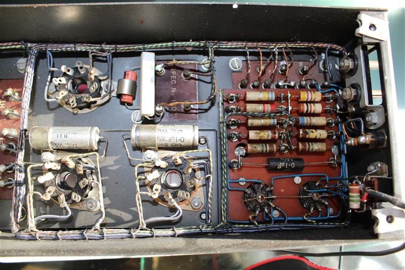
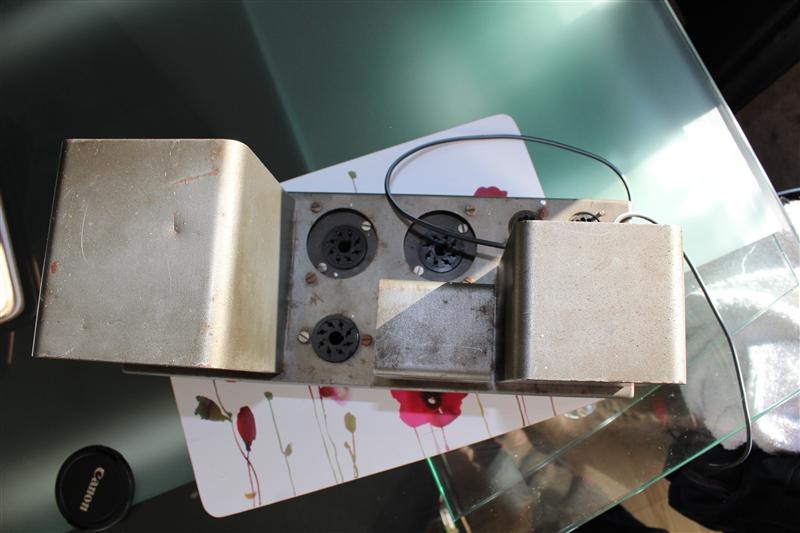
Today I stripped out every component and got the metalwork ready to be re-worked. I also decided to test all the components.
Resistors:
I measured 10 of the resistors and 4 of them were high by over 20% the others seemed quite spot on. However I want to replace them all for modern ones; my thinking is these are the cheap components and if these went wrong it could ruin one of the more expensive items in the chassis. I would like for them to all look the same just for neatness; however I have just thought that in doing so and using say 3W resistors everywhere I could infact be doing away with some level of safety: if somthign goes wrong the resistor may blow open if it was a low wattage and save one of the expensive items..... a quandry for now.
Capicitors:
The steel cased TCC item reads low on both sides, 13.8 and 11.7 as opposed to 16 and 16uF.. I am undecided of what values to use here.
The 350v Hunts are both spot on 0.101 and 0.113uF thats good, I will put them in the spares box and replace them in these amps.
The 150v Hunts is high at 0.163uF
I may still get some of the teflon ones as they are not that expensive but Ill see how my budget goes.
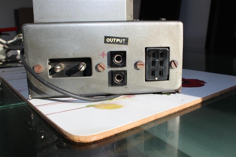
I want to do some mods to this amp mainly for safety, I want to add an earth to the chassis and a safer electrical socket like a modern IEC, I want to use these and have children so I feel its my duty to think about these issues. I also dont want cables coming out the front and back, I knwo its not very purist, but these amps are not the rarest of things so should I want a set of original ones I could always find another set.
Today I stripped out every component and got the metalwork ready to be re-worked. I also decided to test all the components.
Resistors:
I measured 10 of the resistors and 4 of them were high by over 20% the others seemed quite spot on. However I want to replace them all for modern ones; my thinking is these are the cheap components and if these went wrong it could ruin one of the more expensive items in the chassis. I would like for them to all look the same just for neatness; however I have just thought that in doing so and using say 3W resistors everywhere I could infact be doing away with some level of safety: if somthign goes wrong the resistor may blow open if it was a low wattage and save one of the expensive items..... a quandry for now.
Capicitors:
The steel cased TCC item reads low on both sides, 13.8 and 11.7 as opposed to 16 and 16uF.. I am undecided of what values to use here.
The 350v Hunts are both spot on 0.101 and 0.113uF thats good, I will put them in the spares box and replace them in these amps.
The 150v Hunts is high at 0.163uF
I may still get some of the teflon ones as they are not that expensive but Ill see how my budget goes.
I want to do some mods to this amp mainly for safety, I want to add an earth to the chassis and a safer electrical socket like a modern IEC, I want to use these and have children so I feel its my duty to think about these issues. I also dont want cables coming out the front and back, I knwo its not very purist, but these amps are not the rarest of things so should I want a set of original ones I could always find another set.
The resistor you have in the amp are old style kiwame resistors.
You can get modern kiwame resistors from the link below. They are the same thing but with better heat loss.
The other link is for good substitute dual caps. The old TCC cap is worth keeping as is the hunts cap.
The TCC may now have wax and pulp inside instead of paper and oil, or maybe it only needs to be re-polarised
ps............ the centre foil of the dual caps goes to ground
kiwame resistor page
Cricklewood Electronics - CCTV. CCTV Equipment. CCTV Systems. Digital CCTV Cameras
Several replies:
The power supply TCC caps were never paper-in-oil. The very first ones indicated a plain and etched foil terminal; things only relevant to electrolytics.
Some renovators desire to keep them. Unfortunately it is often a question of either an optimally working amplifier, or an exact replica - one sadly can often not have both. I try to decide what Peter Walker would have used today.
One must be careful of 50 year old electrolytic capacitors. Reading on the internet it is clear that that is beyond the proper working life of 'then' electrolytics. It is not only a question of reforming (which also needs to be done controlled - see the Cornell-Dubilier pages a.o.). E.g. one needs to examine the vent. If the capacitor has vented at all or even if the rubber on the vent is cracked, chances are that oxygen has migrated in and the capacitor has deteriorated. Yes, they might last another x years, but I prefer to go the extra mile and restore. (Perhaps a poor comparison, but if one restores a veteran car one machines missing/broken parts according to the original design - but one does not use 100-year old fatigued steel.)
Clintek,
The tolerances you state is perhaps not unacceptable (remember the electrolytic cap tolerance of "-20% - +50%.") But as said above. Then I do not like to install capacitors which cannot handle at least the full h.t. voltage. During warm-up it is unpredictable what values might momentarily be reached. Valves are not 100% equivalents, etc. In this case a minimum of 400V, or why not 630V types; again they are cheap and small nowadays. Back in those days such was scarce, expensive, etc.
And if parts are inaudible why modify the amp at all, apart from making sure all parts are within working spec? Please be my guest - use any resistors, any caps, whatever you like, and then live with the results. Excuse me if I don't.
Neither my desire to perpetuate this - all such debates having an element of "my-father-is-better-than-your-father" is fully predictable.
But with respect Andy: the above bit was not worthy of you! Surely that is not what I meant; it unfortunately gives the impression of a pre-decided idea on your side that you are right regardless.
I agree with your explanation of your psychological procedures, but it contains one basic flaw; there are inviolable laws in science, which no tendency, perception, bio-rythms or influence-of-mood can alter. And I would credit you especially by way of your training to know about subjectivity. A quite elementary study will reveal to what degree hearing (as with all our senses) can be mislead. [Griesinger, Thomatis, Doug Self et al - (yes, Self holds an M-degree in psychology inter alia!)]
Science is not democratic. One cannot sometimes disregard the same laws which one obeys the next day. You are in disagreement with the laws of Kirchoff and Ohm, not with me - I am just the messenger. If you want to glibly disagree with that, be my guest - or rather the guest of Kirchoff and Ohm in this case.
I am not disrespectful here, Andy, only there are several sides to this story. Human perception has been researched and blind-tested to death by several prestigious universities; surely I do not need to explain the findings to you?
But off-topic; thought I would at least take one opportunity to reply. Apology, Clintec.
- Status
- This old topic is closed. If you want to reopen this topic, contact a moderator using the "Report Post" button.
- Home
- Amplifiers
- Tubes / Valves
- My QUAD 2 Restoration