the 6sn7 should be what you call the phase split inverter its what drive the output tubes there shoud a be a 2nd 6sn7 driving the first 6sn7 the gain or guts comes from the pre driving into the 2nd 6sn7 witch then drives the 1st 6sn7 the phase tube its what we call drive/phase/output the 6sn7 is the big daddy to the 12ax7 i have added data sheetsDoes the 6sn7 have guts to drive a quad of kt88s in push pull parallel.
in a Williamson configuration that is.
id assume so since the 12au7 drives kt88s in normal P-P in many circuits,
and the 6sn7 seems to be alot like it but just bigger and more linear.
any suggestions?
abd some circuts to give you a idear
Attachments
![playmast_116[1].jpg](/community/data/attachments/296/296135-1d0efd3e88b57491accc6268df9d2c6d.jpg)
6sn7 is the big daddy to the 12ax7 i have added data sheets
abd some circuts to give you a idear
so i take it two 6sn7s one for gain and one for phase driving 4 kt88s is viable.
i thought the 6sn7 was more like the 12au7 because of gain factor.
so i take it two 6sn7s one for gain and one for phase driving 4 kt88s is viable.
i thought the 6sn7 was more like the 12au7 because of gain factor.
12ax7 will be better 12au7 to low if you are using it for guitar amp i buit such a amp with 12ax7 and it worked very well
12ax7 will be better 12au7 to low if you are using it for guitar amp i buit such a amp with 12ax7 and it worked very well
thought guitar amplifiers ect was for another forum.
thought guitar amplifiers ect was for another forum.
12ax7 will work fine 3 12ax7 and your kt88's it will rock you have circuit
12ax7 will work fine 3 12ax7 and your kt88's it will rock you have circuit
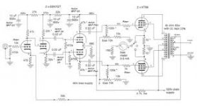
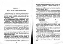
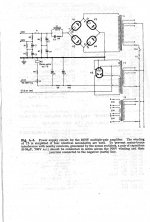
trying to pull off an octal tube only amplifier, a 6sn7 driver phase kt88 PPP stereo amplifier has being floating on my mind alot recently.
GEC developed a circuit for Multiple Kt 88 using 6SN7's. The amp uses a 6SN7 cathode follower to drive the out put stage for low impedance drive.
The last tube you would want to use to drive KT88's or 6550's is a 12AX7 they are hi mu high plate resistance, high distortion tubes and no good as drivers, nothing like a 6SN7 which is low mu, low plate resistance, low distortion and excellent driver.
Can scan the circuit if any one interested but it is on the Net
Phil
GEC developed a circuit for Multiple Kt 88 using 6SN7's. The amp uses a 6SN7 cathode follower to drive the out put stage for low impedance drive.
The last tube you would want to use to drive KT88's or 6550's is a 12AX7 they are hi mu high plate resistance, high distortion tubes and no good as drivers, nothing like a 6SN7 which is low mu, low plate resistance, low distortion and excellent driver.
Can scan the circuit if any one interested but it is on the Net
Phil
remember reading that the 6sn7 was the third most linear vacuum tube triode, came second if you count the fact that the 2 before it where just the same tube with different heater, think it was called something like 56,76.
an PPP kt88 style amplifier using 6sn7 as gain/driver whould be most interesting.
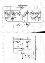
GEC KT88/6550 amp: GEC recommends this design when using 4 or more KT88. I have used this circuit to drive 2A3's using 12BH7 and 6BL7's to get the extra drive required for 2A3's. KT88's are much easier to drive.
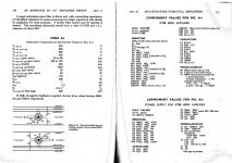
some questions regarding that circuit, why is there a cap+resistor going plate to plate on the output tranny,
and why is the same found on the screen grid to plate. ? (c10 r60) and (c8 r58)
The thing to remember is that the KT88 has a spec for maximum grid-cathode resistance: 220K in case of cathode bias; 100K in case of fixed bias. Those would be halved for PP-parallel operation, i.e. 50K for fixed bias.
Then, to drive KT88s with any linearity, the driver Rl should be lower, of the order of some 15K. This ratio is also important as the driver anode will have to deliver >100Vpp.
This is pretty tight even for a 6SN7. I quickly visited the anode graphs. Assuming an h.t. of 400V and an anode load of 15K, one finds a suitable operating point at Va = 270V, Ia = 10mA with Vg1 = -8,5V. That gives a Pa = 2,7W, still within the limit of 3,7W for both triodes working, so all still well (these calculations should be refined to include the Rg=50K in the mix). It might be better for other reasons to drive with cathode followers, but that is another discussion - the above would still be ball-park extremities.
why is there a cap+resistor going plate to plate on the output tranny, and why is the same found on the screen grid to plate. ? (c10 r60) and (c8 r58)
The RC's act both as Zobels, maintaining a defined and resistive-ish load to the valves, and as dampers for the inductive spike from dI/dt at valve turnoff. While the valve is turned off it's incapable of damping the ringing; transformer coupling to the other polarity valve is imperfect so _it's_ not completely capable; yada yada.
All good fortune,
Chris
The extra parts{ R58 C8,ect} are to prevent Ultrasonic Oscillation.The values depend on the quality of the out put transformers. I used the recommended Sowter transformers.2.2k P to P
I have scanned the rest of the Artical. I have never used more than 4 tubes.
Phil
I have scanned the rest of the Artical. I have never used more than 4 tubes.
Phil
Attachments
Strange,
nobody маке note for Kevin Carter excellent design:
http://www.kandkaudio.com/images/PPAmpInput.pdf
Even without anode choke, just with CCS's in a cathode of LTP, its a
very promising.
nobody маке note for Kevin Carter excellent design:
http://www.kandkaudio.com/images/PPAmpInput.pdf
Even without anode choke, just with CCS's in a cathode of LTP, its a
very promising.
Strange,
nobody маке note for Kevin Carter excellent design:
http://www.kandkaudio.com/images/PPAmpInput.pdf
Even without anode choke, just with CCS's in a cathode of LTP, its a
very promising.
i want to try to avoid inner-stage transformers.
i am asking if an amplifier based on 2 6sn7's and 4 kt88s pr channel is viable.
i want to try to avoid inner-stage transformers.
i am asking if an amplifier based on 2 6sn7's and 4 kt88s pr channel is viable.
My 6SN7/KT88 amp has 3 6SN7s one for phase splitter and the other 2 for driver duty; paraphase circuit push pull.
Cheers,
Bob
- Status
- This old topic is closed. If you want to reopen this topic, contact a moderator using the "Report Post" button.
- Home
- Amplifiers
- Tubes / Valves
- 6sn7 driving Push Pull Parallel kt88's?