my short answer is: Yes, it's a very, very viablei want to try to avoid inner-stage transformers.
i am asking if an amplifier based on 2 6sn7's and 4 kt88s pr channel is viable.
")
anyway, Interstage transformers, when used properly, are great path to your audio nirvana (personal opinion)
Best luck!
i want to try to avoid inner-stage transformers.
i am asking if an amplifier based on 2 6sn7's and 4 kt88s pr channel is viable.
There are two straightforward circuits I can think of that would work driving paralleled KT88 in pentode or ultralinear configuration (not necessarily triode).
- LTP phase splitter to push-pull driver
I've built this with a 6DJ8 or 12AT7 as the LTP-phase splitter (first stage) and a 6GU7 (equivalent to 12BH7) PP driver, into PP 2A3 triodes. It turned out quite well. I imagine a pair of 2A3's are a tougher load than PPP KT88 pentodes.
The LTP/phase splitter will need a negative supply for its tail.
If you can DC couple the first stage LTP/phase splitter to the second stage PP driver, you can end up with only one RC coupling. That would simplify the application of feedback.
- Williamson
The Williamson would be capable of more voltage swing for a given B+. That might be important if you want to add gobs of NFB around the amp. It also does not require a negative supply, so is simpler. The downside is that there will be two RC couplings in the circuit, which makes the application of feedback more complicated (increased likelihood of instability).
Either should work well with 6SN7 -> 6SN7 -> PPP KT88
That GEC circuit multi posted is interesting, but uses more tubes, doesn't it?
--
I found an old post of a driver made by tubelab for driving triode-wired 6L6GC to AB2:
http://www.diyaudio.com/forums/atta...1241491772-6l6gc-ab2-amp-ltp_driver_board.pdf
That's an LTP/phase splitter first stage, PP driver second stage, into MOSFET emitter followers to drive the output stage grids. That should be more than capable of driving PPP KT88 pentodes. You may or may not need to modify the circuit to get the proper voltage swing out for your KT88's, depending on how you plan on running your KT88's.
That's like that GEC circuit in a way, but using MOSFET emitter followers instead of tube cathode followers to drive the output stage. The MOSFET followers won't need tube sockets!
If you have "Valve Amplifiers" by Morgan Jones, check out the Crystal Palace amplifier for yet another version of this topology.
In your case, this style of amp might work better with 6SL7 LTP/phase splitter -> 6SN7 PP driver, and then either RC couple to the KT88 grids or emitter followers, depending.
--
Last edited:
There are two straightforward circuits I can think of that would work driving paralleled KT88 in pentode or ultralinear configuration (not necessarily triode).
- Williamson
The Williamson would be capable of more voltage swing for a given B+. That might be important if you want to add gobs of NFB around the amp. It also does not require a negative supply, so is simpler. The downside is that there will be two RC couplings in the circuit, which makes the application of feedback more complicated (increased likelihood of instability).
Either should work well with 6SN7 -> 6SN7 -> PPP KT88
That GEC circuit multi posted is interesting, but uses more tubes, doesn't it?
--
i want to be able to run it triode/UL so 3 6sn7's is a must for good sound?
i thought Williamson, but not tons of negative feedback, maybe 6db +-.
And now we have the three classic push-pull tube amp circuits, again.
1) "Dual differential" - LTP (with CCS) DC coupled to PP driver RC coupled to outputs
2) "Williamson" - common cathode stage DC coupled to cathodyne phase splitter RC coupled to PP driver RC coupled to outputs
3) "Mullard 5-20" - common cathode stage DC coupled to LTP (Schmitt inverter) RC coupled to outputs
--
Last edited:
And now we have the three classic push-pull tube amp circuits, again.
1) "Dual differential" - LTP (with CCS) DC coupled to PP driver RC coupled to outputs
2) "Williamson" - common cathode stage DC coupled to cathodyne phase splitter RC coupled to PP driver RC coupled to outputs
3) "Mullard 5-20" - common cathode stage DC coupled to LTP (Schmitt inverter) RC coupled to outputs
--
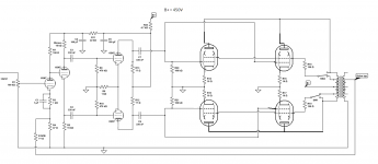
this is what i threw together just now, aiming for 100 watt to 120ish.
two 100 watt 5k PP transformers in parallel, that is a 2.5k plate load.
Attachments
Of course you mean something different for R7. R13 and R12 can be about 25K Ohms. And don't forget G1 grid stops for the output valves - very important. And bias!
All good fortune,
Chris
yes, i didnt care to add the grid stoppers and bias to the schematic, since they are not really critical at this stage.
DTN Williamson's own notes about the low frequency poles are still definitive (and, sadly, too often overlooked). They can be found in his follow-up letters to the construction project. Very very highly recommended.
All good fortune,
Chris
Where can these letters be found?
Low frequency poles? high frequency poles? im getting in at uncharted theretory here, i assume its about radio frequency oscillation and ultra low frequency oscillation.
Ruben,
Butting in on Chris' post,
Low frequency poles: Sort of about l.f. oscillation (instability really). But one should not be upset by that. I would e.g. not lower nfb as a cure. The requirements for stability are quite easy, if occasionally involving high µF capacitors, but that is not a problem these days. I have a design for a 100W tube power amplifier involving 4 l.f. capacitor time constants apart from the OPT, and it is quite stable at about 22dB of signal nfb.
(As said, h.f. stability is more difficult as it involves unknown capacities from e.g. wiring. That one sorts out on the bench with the aid of a signal generator and an oscilloscope. Tests are often shorter than maths if one has the general idea!)
Where can these letters be found?
Low frequency poles? high frequency poles? im getting in at uncharted theretory here, i assume its about radio frequency oscillation and ultra low frequency oscillation.
His amplifier papers were reprinted some years ago, but don't pay the ridiculous price asked here (it was originally about $5.00 US):
The Williamson amplifier: A collection of articles reprinted from Wireless World on Design for a high quality amplifier: David Theodore Nelson Williamson: Amazon.com: Books
He discusses what is now, in the age of op-amps, called a single dominant pole compensation, but for low frequencies. If you want to build a feedback amplifier, you're about to learn something about feedback. An excellent start is to learn about op-amps.
All good fortune,
Chris
Another subject i thought of is what output transformer is better suited for this task, and output impedance, i have seen single pairs of kt88's run on around 4k, so i assume somthing around 2k whould be ideal.
hammond has a 120 watt tranny that is 1.9k, (1650TA)
Hammond Mfg.-"Classic" Push-Pull-Easy Wire-Tube Output Transformers - (1608A-1620A, 1645A & 1650A Series)
hammond has a 120 watt tranny that is 1.9k, (1650TA)
Hammond Mfg.-"Classic" Push-Pull-Easy Wire-Tube Output Transformers - (1608A-1620A, 1645A & 1650A Series)
another company, Lundahl Transformers - Tube Amplification Output Transformers
Ruben,
and it is quite stable at about 22dB of signal nfb.
The proof of the design is how much more feedback on top of this is required before instability commences at either the LF or HF end or both ?
richy
Last edited:
Another subject i thought of is what output transformer is better suited for this task, and output impedance, i have seen single pairs of kt88's run on around 4k, so i assume somthing around 2k whould be ideal.
hammond has a 120 watt tranny that is 1.9k, (1650TA)
Hammond Mfg.-"Classic" Push-Pull-Easy Wire-Tube Output Transformers - (1608A-1620A, 1645A & 1650A Series)
Im by far no expert at all, but I would not take it for granted that doubling the tubes automaticly means half impedance load on trafo
you may also have to consider a change in supply voltage and bias current
The proof of the design is how much more feedback on top of this is required before instability commences at either the LF or HF end or both ?
richy
i am not sure if the gain is high enough for that kind of negative feedback, adjustment of feedback is pretty easy tho on a Williamson, just one resistor to play with.
Im by far no expert at all, but I would not take it for granted that doubling the tubes automaticly means half impedance load on trafo
you may also have to consider a change in supply voltage and bias current
According to good ol' Morgan Jones, yes, you need to halve the plate-to-plate load and double the current capacity of the power supply. Plate voltage and grid bias remain the same.
So if you had a circuit with a single pair of KT88 run with a +450V plate voltage, -50V grid bias, a plate current of 75mA per tube (150mA total for the pair), into a plate-to-plate load of 4k ohms, then for the push-pull-parallel set of KT88's, the plate voltage would remain the same, the grid bias would remain the same, the plate current would still be 75mA per tube (so 300mA for four), but the plate(s)-to-plate(s) load impedance would be halved to 2k ohms.
Unless I'm terribly wrong, of course... Or you decide to change the operation point for your KT88's...
- Status
- This old topic is closed. If you want to reopen this topic, contact a moderator using the "Report Post" button.
- Home
- Amplifiers
- Tubes / Valves
- 6sn7 driving Push Pull Parallel kt88's?