It looks like they measure inductance with low voltage at just over 1V (which would mean very low output power in typical amplifiers). It's superpermalloy so the initial permeability is very high and has quite less hysteresis losses than iron. At higher voltage L will improve (until the onset of saturation).
I assume there is just a tiny natural gap which might allow 10-20 microamps and still able to pass about 80% of the signal in comparison to no grid current at all. I don't think they can manage much more than that as they do not write about permissible DC current and they use small cores.
I assume there is just a tiny natural gap which might allow 10-20 microamps and still able to pass about 80% of the signal in comparison to no grid current at all. I don't think they can manage much more than that as they do not write about permissible DC current and they use small cores.
Last edited:
45, I have four of them here already...so, what would be your advise how to connect them (see my questions above...) ?
The experiment with my amorphous IT from Monolith will be another experiment, but a separate one.
In your schematic I think you can only swap the 39K grid resistor with choke and increase the coupling cap. Try 1-4uF range.
To tame the subsonic peak, as suggested by Kevinkr previously, you could add a resistor in series with the choke. However this could be a solution only if a small value would work. If you have to add some 10K-22K it doesn't make much sense because in your circuit the grid resistor is just 39K.....
In the end that circuit will work better as it is, IMO. I would not waste time with those chokes and go straight with the IT.
Last edited:
I like my grid chokes. The ones I am using are 640H @120Hz 2500H @ 20Hz and 20K DC resistance. I have a scope and a sine/square wave generator so what should I look for that would show that they are behaving badly?
I'm using a 1uF coupling cap to the grid choke attached to the grid of my GM70.
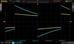
Here is a 50Hz square wave. Yellow trace is a 100X probe on the grid of the GM70 and Blue is the output transformer output.
I'm using a 1uF coupling cap to the grid choke attached to the grid of my GM70.
Here is a 50Hz square wave. Yellow trace is a 100X probe on the grid of the GM70 and Blue is the output transformer output.
Attachments
I like my grid chokes. The ones I am using are 640H @120Hz 2500H @ 20Hz and 20K DC resistance. I have a scope and a sine/square wave generator so what should I look for that would show that they are behaving badly?
I'm using a 1uF coupling cap to the grid choke attached to the grid of my GM70.
Here is a 50Hz square wave. Yellow trace is a 100X probe on the grid of the GM70 and Blue is the output transformer output.
You can't see how much THD you have from that square wave. Moreover it is just 50Hz. I don't say 20Hz (although RC coupling has no problem to work fine down to such frequency if no grid current) but at least 30Hz?
However the main point is another one and is a bit more general. From your picture I don't think there is any significant grid current. What happens if there is grid current (i.e. max Pout)? If the choke cannot withstand DC current it will introduce distortion because saturates very easily. Of course saturation happens first at low frequency because the induction is inversely proportional to frequency. Grid chokes are supposed to reduce the bias shift caused by large resistors due to grid current but in reality they just can't cope with that.
If there is no grid current even at max Pout then the RC coupling might be even better (with the right driver and passive components).
Last edited:
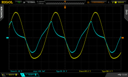
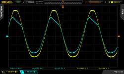
Here is max power out pictures at 100 Hz and 20Hz. I'm thinking we are pulling a bit of grid current here.
100 Hz is 42 watts out 16.98V into 6.8 ohms
20 Hz is not very friendly to the output transformer. But the grid choke looks to be holding it's own??
Yellow trace is grid of GM70. Blue trace is output of amp into 6.8 ohms.
100 Hz is 42 watts out 16.98V into 6.8 ohms
20 Hz is not very friendly to the output transformer. But the grid choke looks to be holding it's own??
Yellow trace is grid of GM70. Blue trace is output of amp into 6.8 ohms.
Attachments
Here is max power out pictures at 100 Hz and 20Hz. I'm thinking we are pulling a bit of grid current here.
100 Hz is 42 watts out 16.98V into 6.8 ohms
20 Hz is not very friendly to the output transformer. But the grid choke looks to be holding it's own??
Yellow trace is grid of GM70. Blue trace is output of amp into 6.8 ohms.
That yellow trace shows clear distortion. I would guess no less than 5%. Likely more @ 20 Hz. If that is the input of the GM70 the output will be generally worse independently of the output transformer.
Last edited:
I did some distortion measurements years ago. I will see if I can set it up again.
Remember the 42 watts out is way over driven. I will see what I can come up with.
I guess the whole thing here is does the grid choke cause the distortion? Do you see the grid choke causing anything obvious here? I'm going to build a PSE GM70 amp (fixed bias) Using grid chokes makes it easy. But I could do it other ways.
I did some distortion measurements years ago. I will see if I can set it up again.
Remember the 42 watts out is way over driven. I will see what I can come up with.
I guess the whole thing here is does the grid choke cause the distortion? Do you see the grid choke causing anything obvious here? I'm going to build a PSE GM70 amp (fixed bias) Using grid chokes makes it easy. But I could do it other ways.
It is obvious that the input at the GM70 is quite distorted. So the grid choke is not giving any benefit for me. The yellow trace (i.e. the grid signal) is distorted. It is not simmetrical at all and this can already be 5% THD o more, IME. Then the one at 20Hz is clearly saturating.
The maximum output power is not important. The question is if the grid choke is a real replacement for the grid resistor. The main reasons why one puts a grid choke are: 1) A too large grid resistor cannot be used 2) to reduce the bias shift due to grid current and have a cleaner drive.
If the choke cannot get a clean drive why should I use it? A SE driver delivering 150-200 V P-P with low THD and no feedback at least down to 30Hz is possible. It's not trivial. That's it.
If I cannot use a large resistor for the GM 70 grid I can use a DC coupled source/cathode follower or an appropriate transformer that can cope with DC current and pass the required signal with less distortion than above. Such a transformer is not cheap so the viable alternative is a cathode follower (which works also better despite myths!). This is not that difficult, especially if one is not interested in deep positive grid drive. Have a look at Audio Notes using the 211. That is one good example.
Of course you can build the PSE with grid chokes and likely will never get to the point of grid current but this will not solve the problem and has a price (240VA just to switch on the filaments of 4 GM70's). That's your choice and you pay the bill so I don't mind.....
Last edited:
But it will heat my house in the winter.Of course you can build the PSE with grid chokes and likely will never get to the point of grid current but this will not solve the problem and has a price (240VA just to switch on the filaments of 4 GM70's). That's your choice and you pay the bill so I don't mind.....
I will look at the Audio Note 211. Thanks!
But it will heat my house in the winter.
I will look at the Audio Note 211. Thanks!
The Audio Note example is more useful on how to get a dual supply from a single secondary with no center tap. Likely in your case, as the bias and voltage drive are rather high, you might need some trick that allows you to employ a useful cathode resistor passing enough current but without getting too high anode voltage on the tube. You might ask "tomchr" some suggestions about the mosfet in the plate of his 6N6P cathode follower driving the 300B.
A good candidate for your cathode follower might be the 6BL7.
- Status
- This old topic is closed. If you want to reopen this topic, contact a moderator using the "Report Post" button.
- Home
- Amplifiers
- Tubes / Valves
- Grid choke considerations for 300b