QE08/200 push-pull amp.monoblocks...
i have always wanted to build an 813 push-pull power amp,
but the B+ of 1500vdc is way too high for me...
then at about 2008, Gerry Sta. Maria(+632-400-2762),
my regular tube pimp, gave me a quad of of these tubes.....
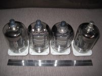
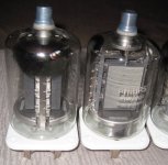
QE-08/200 tubes made by Philips...
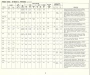
datasheet here: Page not found - Richardson Electronics
the tube has 3 cathodes in parallel so that at 6.3volts, filament draw is 3.9A,
now this is about the same as a quad of 6L6GC tubes....
picture of the tube side by side with the more popular KT88 and EL34...
i know of no other tube bigger than this one that can deliver big powers at sub 1kv voltage levels.....
this tube made by Philips is diy'er friendly...
````````````````````````````````````````````
Design Steps:
1. Choose QE08/200 operating point for push-pull class AB2....
B+ = 750vdc
G2 = 250vdc
Vg1 = -45volts
Ipmax = 2 x 280mA
Ig2max = 2 x 40mA
Ig1max = 2 1mA
Vg1pk-pk = 110volts
anode load of 3500ohms plate to plate
2. Design of power traffo:
2.1 total power input to tubes = [(2 x 210)+(2 x 10)]watts = 440watts
2.2 required filament power for output tubes = 4 x 3.9A x 6.3vac = 98watts
2.3 required filament power for preamp/driver tubes = 6.3vac x 3A = 18.9 watts
2.4 power required by preamp/driver tubes = 20 watts (estimated)
2.5 total power required from power traffo secondary = 440 + 98 + 18.9 + 20 = 576 watts
2.6 required power traffo VA rating = 576watts/0.6 = 961 volt-amperes
2.7 as per RDH4, required power traffo must at least have a core area A(in square inches)
equal to Sqrt(VA)/5.58, so A = [sqrt961]/5.58, or 5.56 square inches...
there are many core sizes that can satisfy this requirement, i choose a core with 2 inch center leg,
stacking to about 3.5 inches.
2.8 now that we have a core, we can now determine the required voltages...
2.9 Datasheet specifies a B+ of 750vdc means that that is the B+ at full power,
so that we have to design for higher standby voltage, i select 75volts higher so that out B+ will idle at 825vdc....
it is normal for a tube psu to sag big under load...
2.10 Votage doubler will be employed, so that the secondary ac required becomes 825vdc/2.8 = 294 volts...
required current rating of this winding = 440/750 = 0.59A, using a #19 wire allows 1.8A at 700cm/ampere,
way more than what is requried...
2.11 fixed biasing will be used and a bias or -45 volts will need a dc of more than 100volts or say 150volts,
again this will be a voltage doubler type to enable the use of mosfet source followers
to directly drive the grids of the QE08/200, required ac winding is 150/1.4 = 107volts ac, #24 wire is to be used here..
2.12 for the preamp and driver tubes, a separate 450volt dc supply will be required,
ac winding is 450/1.4 = 325vac, #29 wire is to be used here...
2.13 we will calculate primary winding at 230volts ac, primary turns = 1750/6 = 290 turns,
we will use #17 wire, turns per volt, t/v then equals 290/230 = 1.27turns per volt....
2.14 now we look at the filament windings, because of the huge filament currents,
i decided to series connect the power tube's filaments,
so that 12.8 volts is required, 16 turns #15 x 2 strands....
2.15 coil table summary:
primary......290turns of #17 magnet wire
secondary 1.......373 turns of #19 magnet wire
secondary 2.......135 turns of #24 magnet wire
secondary 3.......412 turns of #29 magnet wire
filament1..........16 turns of 2 x #15 magnet wire
filament2..........8 turns of 2 x #18 magnet wire
2.16 Estimated copper weight at 2kg and core steel weight at 10kg,
weight of built up traffo without covers is about 12kgs...
this more or less completes our transformer design,
actual number of turns tend to change during actual build, this is quite normal...
3. Design of output traffo:
3.1 looking at typical traffo designs on the web, a 300 watt traffo tends to be bulky,
here i choose to use a 1 3/4 inch center leg, 0.35mm Z11(M6) cores...
3.2 a 3 inch nylon bobbin is used here....so with with a 3 x 1.75 inch core area,
power handling (as per RDH4) at 60hz is given as 860 watts, so that at 30hZ,
this is about 430 watts,and at 20hz about 290watts....use of this type of core arrangement is to my mind justified....
3.3 Anode to anode load is given as 3500 ohms, 4, 8 and 16 ohm secondaries are provided to accommodate
various speaker power and impedance configurations...
i.e. an 8ohm speaker connected to the 4ohm tap while giving less power reflects a 7k primary impedance...
connecting a 4 ohm speaker on the 8 ohm tap theoretically doubles power due the halved reflected primary impedance....
this amp then becomes very versatile in terms of speaker matching...
3.4 these are completed output traffos:
3.5 pictures of the OPT's in various stages of construction:
i have always wanted to build an 813 push-pull power amp,
but the B+ of 1500vdc is way too high for me...
then at about 2008, Gerry Sta. Maria(+632-400-2762),
my regular tube pimp, gave me a quad of of these tubes.....
QE-08/200 tubes made by Philips...
datasheet here: Page not found - Richardson Electronics
the tube has 3 cathodes in parallel so that at 6.3volts, filament draw is 3.9A,
now this is about the same as a quad of 6L6GC tubes....
picture of the tube side by side with the more popular KT88 and EL34...
i know of no other tube bigger than this one that can deliver big powers at sub 1kv voltage levels.....
this tube made by Philips is diy'er friendly...
````````````````````````````````````````````
Design Steps:
1. Choose QE08/200 operating point for push-pull class AB2....
B+ = 750vdc
G2 = 250vdc
Vg1 = -45volts
Ipmax = 2 x 280mA
Ig2max = 2 x 40mA
Ig1max = 2 1mA
Vg1pk-pk = 110volts
anode load of 3500ohms plate to plate
2. Design of power traffo:
2.1 total power input to tubes = [(2 x 210)+(2 x 10)]watts = 440watts
2.2 required filament power for output tubes = 4 x 3.9A x 6.3vac = 98watts
2.3 required filament power for preamp/driver tubes = 6.3vac x 3A = 18.9 watts
2.4 power required by preamp/driver tubes = 20 watts (estimated)
2.5 total power required from power traffo secondary = 440 + 98 + 18.9 + 20 = 576 watts
2.6 required power traffo VA rating = 576watts/0.6 = 961 volt-amperes
2.7 as per RDH4, required power traffo must at least have a core area A(in square inches)
equal to Sqrt(VA)/5.58, so A = [sqrt961]/5.58, or 5.56 square inches...
there are many core sizes that can satisfy this requirement, i choose a core with 2 inch center leg,
stacking to about 3.5 inches.
2.8 now that we have a core, we can now determine the required voltages...
2.9 Datasheet specifies a B+ of 750vdc means that that is the B+ at full power,
so that we have to design for higher standby voltage, i select 75volts higher so that out B+ will idle at 825vdc....
it is normal for a tube psu to sag big under load...
2.10 Votage doubler will be employed, so that the secondary ac required becomes 825vdc/2.8 = 294 volts...
required current rating of this winding = 440/750 = 0.59A, using a #19 wire allows 1.8A at 700cm/ampere,
way more than what is requried...
2.11 fixed biasing will be used and a bias or -45 volts will need a dc of more than 100volts or say 150volts,
again this will be a voltage doubler type to enable the use of mosfet source followers
to directly drive the grids of the QE08/200, required ac winding is 150/1.4 = 107volts ac, #24 wire is to be used here..
2.12 for the preamp and driver tubes, a separate 450volt dc supply will be required,
ac winding is 450/1.4 = 325vac, #29 wire is to be used here...
2.13 we will calculate primary winding at 230volts ac, primary turns = 1750/6 = 290 turns,
we will use #17 wire, turns per volt, t/v then equals 290/230 = 1.27turns per volt....
2.14 now we look at the filament windings, because of the huge filament currents,
i decided to series connect the power tube's filaments,
so that 12.8 volts is required, 16 turns #15 x 2 strands....
2.15 coil table summary:
primary......290turns of #17 magnet wire
secondary 1.......373 turns of #19 magnet wire
secondary 2.......135 turns of #24 magnet wire
secondary 3.......412 turns of #29 magnet wire
filament1..........16 turns of 2 x #15 magnet wire
filament2..........8 turns of 2 x #18 magnet wire
2.16 Estimated copper weight at 2kg and core steel weight at 10kg,
weight of built up traffo without covers is about 12kgs...
this more or less completes our transformer design,
actual number of turns tend to change during actual build, this is quite normal...
3. Design of output traffo:
3.1 looking at typical traffo designs on the web, a 300 watt traffo tends to be bulky,
here i choose to use a 1 3/4 inch center leg, 0.35mm Z11(M6) cores...
3.2 a 3 inch nylon bobbin is used here....so with with a 3 x 1.75 inch core area,
power handling (as per RDH4) at 60hz is given as 860 watts, so that at 30hZ,
this is about 430 watts,and at 20hz about 290watts....use of this type of core arrangement is to my mind justified....
3.3 Anode to anode load is given as 3500 ohms, 4, 8 and 16 ohm secondaries are provided to accommodate
various speaker power and impedance configurations...
i.e. an 8ohm speaker connected to the 4ohm tap while giving less power reflects a 7k primary impedance...
connecting a 4 ohm speaker on the 8 ohm tap theoretically doubles power due the halved reflected primary impedance....
this amp then becomes very versatile in terms of speaker matching...
3.4 these are completed output traffos:
3.5 pictures of the OPT's in various stages of construction:
Attachments
thanks guys, i am looking at the drive circuit, this amp will be a classAB2, i am using a Mosfet source followers to drive the grids of the output tubes directly...
the front-end will use a Mullard 5-20 type topology, using 6J9 input pentode and 6CG7 LTP.....this is tentative though...
screens are to fed from Mosfet source follower regulators....bias will likely be regulated as well...
the front-end will use a Mullard 5-20 type topology, using 6J9 input pentode and 6CG7 LTP.....this is tentative though...
screens are to fed from Mosfet source follower regulators....bias will likely be regulated as well...
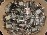
I have a pile of these things. Also known as type 7378. I sold the best ones years ago and kept these. They are all a little weak but still functional.
will you consider selling? sent you email, thanks...
AJT
I bought a large quantity of the QE08/200 from a Military Auction; resold them for hundreds of dollars each. Unfortunately dont have any now.
Would be interested to see the circuit?
Thanks
Great you can make the output transformers!!! Are the winders expensive?
Phil
Phil,
the circuit would be like a Mulard 5-20 or citation 5, but i will use mosfets as source followers....
the output transformer threads here and as well as the internet gave me that push to make my own, my over 30 years winding my own power transformers surely helped...
the winding machine is not expensive, they are cheap china jobs but do the work fine....


- Status
- This old topic is closed. If you want to reopen this topic, contact a moderator using the "Report Post" button.
- Home
- Amplifiers
- Tubes / Valves
- QE08-200