hi,
I´m Tobias, 36, from Germany.
Thanks for this thread, it was very inspiring!
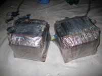
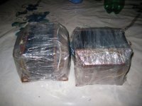
I had some SRS461 tubes (equivalent to QE08-200), an wanted to build a strong monoblock for subwoofer.
My driver stage works with russian 6SN7-GT tubes.
The +250V G2 voltage is stabilized by a 6L6-GB.
All the transformers are custom made by my local dealer.
There are toroidal transformers in the power supply.
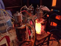
I use four DCG4/1000 mercury rectifier tubes for a nice optic.
The output transformer is a PM135 type.
At the moment, everything is on breadborads and it works fine")
In the next step, I´ll build a stable housing with all the meters, control knobs, etc. needed..
I made a short videoclip about the current state:
https://youtu.be/A9g4UyRjo5Y
ciao,
Tobias
I´m Tobias, 36, from Germany.
Thanks for this thread, it was very inspiring!
I had some SRS461 tubes (equivalent to QE08-200), an wanted to build a strong monoblock for subwoofer.
My driver stage works with russian 6SN7-GT tubes.
The +250V G2 voltage is stabilized by a 6L6-GB.
All the transformers are custom made by my local dealer.
There are toroidal transformers in the power supply.
I use four DCG4/1000 mercury rectifier tubes for a nice optic.
The output transformer is a PM135 type.
At the moment, everything is on breadborads and it works fine
In the next step, I´ll build a stable housing with all the meters, control knobs, etc. needed..
I made a short videoclip about the current state:
https://youtu.be/A9g4UyRjo5Y
ciao,
Tobias
I use four DCG4/1000 mercury rectifier tubes for a nice optic.
ciao,
Tobias
Hi,
When you go to Amplifiers with valves and then look for the EV4418 you will find a schematic diagram of an amplifier with 2 x QE08-200.
Regards, M
When you go to Amplifiers with valves and then look for the EV4418 you will find a schematic diagram of an amplifier with 2 x QE08-200.
Regards, M
Hi Tobias,
thanks for posting your work here, this amp is put on hold for now, i still have a 4d32 mpp amp yo do and then i will do this....
can you give us the operating points of your output stage?
i understand that G2 needed to be fed from a low impedance source..
and that G1 needs a low impedance path to ground. i.e. lower valued grid leaks...
i wonder if smoking-amps "crazy drive" can be used here effectively...
Unfortunately I´m not a specialist in calculating tube circuits.
I use well known templates to experiment with.
G1 works well with -34 to -36V.
With lower voltages, sinus test signals are distorted.
The anode current then is about 0,2A, with G2 at 250V.
The unclipped sinus output power is ~200W.
I think with a better driver circuit, there will be some more output.
^what was your plate voltage and opt anode to anode load?
yes, imho cathode followers like the 6bl7 can do wonders, or the power tubes, like the el34....
hi!
Plate voltage is around 750V under load.
The amp isn't finished yet. It worked very well in the meantime, so it´s still on the breadboard. I´m satisfied with the performance as subwoofer amp.
There is more power than enough to drive a 15" sub.. the level is too intense in the living room at full volume.
After 150 - 200 operating hours, there was suddenly a fatal breakdown of the circuit!
I didn't pay attention for some minutes, and one SRS461 tube was freakin out...

There are rugged high voltage / high current fuses (for solar equipment) in the power supply, but the simple 250V fuse on the plate connection was exploded.. an arc was still burning after that..
ok, a fuse desaster with learning effect.
By analyzing the aftermath, the -36V G1 Bias voltage failed for one SRS461. The Bias voltage for the second tube remained ok.
Unfortunately the anode heat was too much, the glass cracked on the top cap connection, air came in slowly

With a new tube, I was able to reproduce the failure.
Shortly after powering up the amp, one of the two -36V G1 voltages is slowly getting more and more positive!
That takes about 5 minutes, which seems strange to me. There is no grid current at the start, and a slight grid current around some uA, when the voltage is as low as -28V.
Then the anode plates of this tube begin to glow dark red, time to switch off..
All connections and components behind the power supply are ok.
I don´t think there are wild HF oscillations. I suspect the defect around the voltage divider resistors in the power supply.
There are good quality 2W MOX types, I can hardly imagine that one of them failed?
Maybe the wire resistance poti for bias balance is bad. But it´s military grade quality, old russian technology won't fail
Maybe my punishment came with the flying construction on wooden boards .... I'll rework the power supply.
Attachments
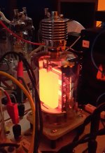
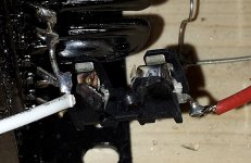
some tubes are run with red plates, others are not...
haha, good one
But I think this is a little bit too much..
The problem seemed to be strange, stayed with several good tubes, even with exchanged places, ... and other oddities.
Power supply tested good.
But noticeable was a much too high G2 voltage with 270V instead of 250V.
I wasn´t able to change this voltage with the poti in the power supply, it had no effect. With the output stage disconnected, 250V in the PS were ok.
This pointed to a defective SRS461 of the first assembly, it seems to have a thermal problem.
If hot enough after ~5mins, theres a grid connection, and voltage flows in direction of G2.
The G2s of both tubes are connected together (1k resistor on each G2) in the power supply, so these stranges things could happen.
The bad tube always let the anode of the healthy tube glow!
With this tube exchanged, the amp works ok again
- Status
- This old topic is closed. If you want to reopen this topic, contact a moderator using the "Report Post" button.
- Home
- Amplifiers
- Tubes / Valves
- QE08-200