Member
Joined 2009
Paid Member
For what it's worth, I built a 2A3 amp that is very similar. The biggest difference is that I used a 12SL7 for the driver (sounds amazing), and I did a bit of a shunt to the PS, just a big bleeder 15ma or so, can't remember exactly. I have tried dozens of different amps and this is the one I'm still listening to a year later. I used the Angela Instruments power transformer and a 5U4 rectifier.
Member
Joined 2009
Paid Member
Member
Joined 2009
Paid Member
Hi Disco - good point, the devil is in the details as always - I shall investigate.
I was also worrying about the topology. The concept of a wimpy driver was looked at before but not in a L-W set-up. The L-W topology I have proposed does not have a bypass capacitor on the cathode resistor of the driver tube which raises it's output impedance.
I'll need to review this. In the meantime, attached is an alternative plan which incorporates a fully bypassed cathode resistor.
Attachments
So, you're abandoning both Loftin and White here ")
Mind that any PS ripple > 15mV will be heard on sensitive (>95dB) speakers.
Besides, all music will be modulated by 120Hz because of that ripple AND
by 60Hz if you light 'm up with AC AND with crossproducts of that.
Take your time, it's no race (look who's talking) ).
Mind that any PS ripple > 15mV will be heard on sensitive (>95dB) speakers.
Besides, all music will be modulated by 120Hz because of that ripple AND
by 60Hz if you light 'm up with AC AND with crossproducts of that.
Take your time, it's no race (look who's talking
) ).I agree that a regulator can be a very good choice. If I were to use a regulator, my personal preference would be to use a shunt regulator. I feel that a shunt regulator puts it's impact on the sonics at a minimum. And if I were to shunt the B+ I would want to use another 2A3. I've seen this approach more than once, the last time I think I read it in Sound Practices. I like it. But I'm not going to use it here because it adds a lot of power dissipation (whether tube or SS it's still a Class A regulator), expense and some complexity. I don't believe we need a regulator if we design the power supply and the amplifier right.
However, we will consider some regulation for the power feed to the input tube
What about a capacitor multiplier rail filter with a chunky cap across its output for starters? Cheap and cheerful, no heat drama, OK not great impedance but to eat ripple for now.
With a mu of 100 the 12AX7 is probably going to provide far more gain than you require, consider the 6J5 if a sensitivity of a couple of Vrms is adequate or the 5842 if you need something on the order of 700 - 800mVrms. I used the 5842 (mu of 42) with great success to drive 71/171, and 45s - nice lively and dynamic sound with very low distortion, works well with LED bias run at about 10mA.. (Choke loading works very well with this tube since rp is low and huge chokes are not required, 100H is enough)
I'd recommend CCS heating for the 2A3, and I've used both IC based CCS and Rod Coleman's boards which I can recommend.. The 2A3 can be AC heated and the audible hum is not too bad, however with AC heating there are significant IM sidebands at 120Hz either side of the fundamental tone being reproduced. Tubelab has discussed and presented results from measurement indicating this is a significant issue. This would generate significant levels of IM on music.
I'd recommend CCS heating for the 2A3, and I've used both IC based CCS and Rod Coleman's boards which I can recommend.. The 2A3 can be AC heated and the audible hum is not too bad, however with AC heating there are significant IM sidebands at 120Hz either side of the fundamental tone being reproduced. Tubelab has discussed and presented results from measurement indicating this is a significant issue. This would generate significant levels of IM on music.
Member
Joined 2009
Paid Member
Quick calculation.
I read on the internet that the miller capacitance of a 2A3 is around 70pF. And since I read it on the internet, it's probably wrong and there are probably opinions on several other choices for this number. But let's go with it for now.
The 12AX7, bypassed cathode resistor, has a plate impedance of around 62k (depending on operating point) and the output impedance is this, in parallel with the plate load, of, say 280k. The answer is around 51k. The signal at the grid will be cut in half when the miller capacitance presents 51k of impedance - which I calculate is well above the 20 kHz audio range.
With an un-bypassed cathode resistor the output impedance shoots up due to the high mu of the tube, to something I calculate as over 150k. Now the high frequencies roll off around just above 14 kHz. And whilst I don't hear too much up there, it's not where I want to take this design. And as for alternative drivers with lower plate resistance, these tend also to have lower mu.
So either the L-W has to get voted off the table, or the high mu driver has to get voted off. I'm going to vote the L-W off the table. I want the sensitivity of the high mu tube. It's not strictly required when you examine the design on-paper, but it has been found to produce nice results by many others who have built amplifiers like this using 12AX7, 6S5F, 7B4 etc.
That's a pitty, I thought the L-W was really neat - I'll file it away for later, maybe I will try it later to find out how it really affects performance.
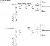
So I need to take another look at ripple. The link posted by Costis leads to one of Broskie's clever ideas (see attached). It's a kind of L-W noise cancellation, but instead of feeding it in to the input tube, it feeds it into the output tube. This might be a viable option.
The other option, is to clean up the B+.
I read on the internet that the miller capacitance of a 2A3 is around 70pF. And since I read it on the internet, it's probably wrong and there are probably opinions on several other choices for this number. But let's go with it for now.
The 12AX7, bypassed cathode resistor, has a plate impedance of around 62k (depending on operating point) and the output impedance is this, in parallel with the plate load, of, say 280k. The answer is around 51k. The signal at the grid will be cut in half when the miller capacitance presents 51k of impedance - which I calculate is well above the 20 kHz audio range.
With an un-bypassed cathode resistor the output impedance shoots up due to the high mu of the tube, to something I calculate as over 150k. Now the high frequencies roll off around just above 14 kHz. And whilst I don't hear too much up there, it's not where I want to take this design. And as for alternative drivers with lower plate resistance, these tend also to have lower mu.
So either the L-W has to get voted off the table, or the high mu driver has to get voted off. I'm going to vote the L-W off the table. I want the sensitivity of the high mu tube. It's not strictly required when you examine the design on-paper, but it has been found to produce nice results by many others who have built amplifiers like this using 12AX7, 6S5F, 7B4 etc.
That's a pitty, I thought the L-W was really neat - I'll file it away for later, maybe I will try it later to find out how it really affects performance.
So I need to take another look at ripple. The link posted by Costis leads to one of Broskie's clever ideas (see attached). It's a kind of L-W noise cancellation, but instead of feeding it in to the input tube, it feeds it into the output tube. This might be a viable option.
The other option, is to clean up the B+.
Attachments
Last edited:
Member
Joined 2009
Paid Member
I'd recommend CCS heating for the 2A3, and I've used both IC based CCS and Rod Coleman's boards which I can recommend.. The 2A3 can be AC heated and the audible hum is not too bad, however with AC heating there are significant IM sidebands at 120Hz either side of the fundamental tone being reproduced. Tubelab has discussed and presented results from measurement indicating this is a significant issue. This would generate significant levels of IM on music.
Kevin - good point, I have been thinking about dc heating:
http://www.diyaudio.com/forums/tube...ment-heater-high-impedance-const-voltage.html
I would like to start off with a.c., the 'old timers' way, and then look at adding a dc supply as a possible enhancement.
Member
Joined 2009
Paid Member
What about a capacitor multiplier rail filter with a chunky cap across its output for starters? Cheap and cheerful, no heat drama, OK not great impedance but to eat ripple for now.
I had to read this twice - Salas talking about a series regulator instead of a shunt
I don't want to use a series regulator, even one this simple. I have read too many reports about their potential impact on the sound. Nelson and others have found that you need 'a lot' of capacitance after a cap multiplier to ensure the signal is not trying to flow through the cap multiplier.
Member
Joined 2009
Paid Member
Member
Joined 2009
Paid Member
Hang on a minute - why can't I bypass the input tube cathode resistor AND apply a L-W topology. Broskie showed the way already, just have to use the capacitors as the divider. The hassle is choosing the right value of the capacitor connecting the cathodes together in order to get good B+ noise cancellation, or else maybe it can still be fine-tuned with a resistor.
Attachments
Member
Joined 2009
Paid Member
Member
Joined 2009
Paid Member
Member
Joined 2009
Paid Member
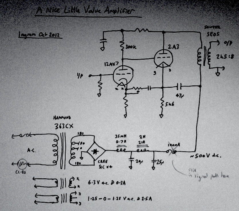
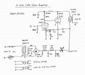
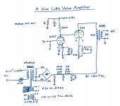
A couple of updates.
I've swapped out the Hammond for an Edcor power transformer (just added it to my order for the 2H choke today).
Added some audiophile bypass caps to a couple of spots.
Added Asano / Shishido - style shunt resistor Rs, which draws current off the supply rail to the driver tube. Along with the resistor to B+ this sets up a voltage divider that stabilizes the supply to the driver tube.
Also added are a couple of snubbers in the power supply, one across the secondary of the power transformer, the other across the output of the bridge rectifier.
Attachments
Have you spun out that power supply yet?
Inductance is quite low so you'll have to use large capacitance to end below 15mV.
Maybe a third filter step, a RC right after the rectifier?
Shoog, did you experiment with ultra low ESR caps on the multiplier?
I did not like it either with Rubicons on the John Linsley Hood circuit.
Did not try others but it tests superflat though
- Home
- Amplifiers
- Tubes / Valves
- A nice little valve amplifier