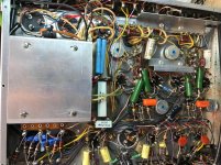
Ok so I just picked up a scott 299, and I believe it is the first generation because of the OPT placement. It came with no tubes, and sold as is but I got it pretty cheap for a project. I plan on pairing with some old Klipsch Heresy's when done.
I am pretty sure the PT is fine, I fired it up with no tubes and I cut the two orange wires for the bias/heater circuit and left them floating due to the hack job I saw when someone "upgraded" the selenium rectifier. All the voltages look good on the secondary and the fuse didn't pop")
I have an 8A 400v silicon bridge rectifier to put in but was curious on the value change for resistor 106, stock is 10R but from what I read on the web most people find that 33R is used to compensate for the more efficient silicon rectifier.
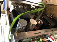
Another question I had with the bias/heater circuit is do the 100-100-10 can capacitors have a common positive connection? It must because of the way they are wired but the schematic shows that the - side of the 100uf caps go to ground. This doesn't make sense to me? Anyway I think the new caps I install will have the - lead at the resistors and the + going to ground.
Ok so output tubes I plan on getting the russian military version of the EL84, I believe they are EL84M and are suppose to be a 7189 replacement.
I am also going to replace all of the black pyramid caps with some orange drops.
I am not sure if anyone else has encountered this but when comparing my amp with the resistance chart they give you my amp was pretty spot on except for R42 and R86. They are suppose to be 680R but measured 680k for both, to boot the color bands on the resistor are correct for 680R but I think they might have been mislabeled.
I am pretty sure the PT is fine, I fired it up with no tubes and I cut the two orange wires for the bias/heater circuit and left them floating due to the hack job I saw when someone "upgraded" the selenium rectifier. All the voltages look good on the secondary and the fuse didn't pop
I have an 8A 400v silicon bridge rectifier to put in but was curious on the value change for resistor 106, stock is 10R but from what I read on the web most people find that 33R is used to compensate for the more efficient silicon rectifier.
Another question I had with the bias/heater circuit is do the 100-100-10 can capacitors have a common positive connection? It must because of the way they are wired but the schematic shows that the - side of the 100uf caps go to ground. This doesn't make sense to me? Anyway I think the new caps I install will have the - lead at the resistors and the + going to ground.
Ok so output tubes I plan on getting the russian military version of the EL84, I believe they are EL84M and are suppose to be a 7189 replacement.
I am also going to replace all of the black pyramid caps with some orange drops.
I am not sure if anyone else has encountered this but when comparing my amp with the resistance chart they give you my amp was pretty spot on except for R42 and R86. They are suppose to be 680R but measured 680k for both, to boot the color bands on the resistor are correct for 680R but I think they might have been mislabeled.
Attachments
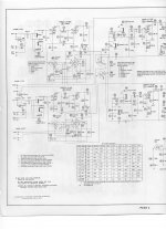
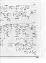
Well, you are correct about the filter capacitors. The drawing is wrong! And the resistors in question should be 680 ohms, not 680K. Part of your problem is that you are looking at a Sams schematic which are prone to errors. Too many stoned heads working there in the 60's. Always use H.H.Scott Schematic Library.
I caution you to not replace any capacitors in the RIAA (or other) equalization circuits with modern fast dielectric types (polyproplyene, polycarbonate, polystyrene, etc) because they will affect the frequency characteristics of the network even if the same values are used. They tend to accentuate higher frequencies. All the other paper capacitors can be replaced with Mylar (polyethylene) orange drops with good results.
An eight amp bridge is overkill, but ok if it fits. And a 33 ohm resistor seems about right although the 10K bias pot would probably take up the excess voltage. And I would put 10 ohm resistors in each 7189 cathode to measure quiescent current across. Scott cheaped-out there.
"Well, you are correct about the filter capacitors. The drawing is wrong! And the resistors in question should be 680 ohms, not 680K."
Thanks that is what I Thought.
"Too many stoned heads working there in the 60's"
LOL!
"I caution you to not replace any capacitors in the RIAA (or other) equalization circuits with modern fast dielectric types (polyproplyene, polycarbonate, polystyrene, etc) because they will affect the frequency characteristics of the network even if the same values are used. They tend to accentuate higher frequencies. All the other paper capacitors can be replaced with Mylar (polyethylene) orange drops with good results."
Thanks for the tip, and that is less soldering that I have to do so that works for me.
"An eight amp bridge is overkill, but ok if it fits"
I know it is overkill but I like how the 8A has it's leads as appose to all the others I saw, and actually it was roughly the same size L x W but just a little fatter.
" And a 33 ohm resistor seems about right although the 10K bias pot would probably take up the excess voltage"
I was more worried about exsessive voltage for the heaters going to valves 1, 2, 6, and 7. I guess I will start with 33R and go from there.
Well I finished up the cap job including all electrolytics and coupling caps (I left a lot of caps in the front/control section of the amp alone including thee RIAA section). I replaced the two 680k resistors on the ECF80's with correct 680R. All plate load resistors were spot on so I left them in, after about a week of listening everythings seems to be good. The amp is dead quiet and sounds fantastic! I can't be happier with the results and I want to thank Hollowstate for the knowledge
The amp is bias to where I read 20v across the big 20w 160R power resistor, but the power transformer is still pretty darn warm after a few hours of operation. Not as hot as some of my guitar amp transformers get but still pretty warm. My question is do people run the amp without the enclosure to dissipate heat? Or does it not really matter?
The amp is bias to where I read 20v across the big 20w 160R power resistor, but the power transformer is still pretty darn warm after a few hours of operation. Not as hot as some of my guitar amp transformers get but still pretty warm. My question is do people run the amp without the enclosure to dissipate heat? Or does it not really matter?
Last edited:
What resistor is that? I see no such resistor in a Scott 299.The amp is bias to where I read 20v across the big 20w 160R power resistor,
I think most schematics show two 360R resistors from pin 8 of 5AR4. I guess I have the less common 299 where Craig from Nosvalves found a schematic where there is just one 20w 160R instead of two 360R 10w. The voltage drop across the resistor in the schematic was 20v so that's what I set it to.
It's funny I just ran across someone else with the same amp in this thread Scott 299 biasing [Archive] - AudioKarma.org Home Audio Stereo Discussion Forums
Craig works on these things all the time and he had to look through his folder to find the schematic so I guess not a lot of these came with one 20w 160R.
I'm sorry but that is not a good or proper way to bias the output tubes at all. Doing it as you said includes current draw from all of the other stages in both channels combined. And it does nothing to measure balance between the two output tubes in either channel. Please go back and read my earlier post about installing a small (10 ohm) 1 watt resistor in each output tube cathode to ground circuit. That's pin 3. Measuring across each resistor will give you each tubes current in terms of voltage. (I=E÷R) Using 10 ohms makes the math super simple.I think most schematics show two 360R resistors from pin 8 of 5AR4. I guess I have the less common 299 where Craig from Nosvalves found a schematic where there is just one 20w 160R instead of two 360R 10w. The voltage drop across the resistor in the schematic was 20v so that's what I set it to.
7189s have a plate dissipation of 12 watts. With 360 volts on the plate, you want quiescent tube current to be around 30 mA max. or less. 30 mA is almost 11 watts. Less is better for tube life. So 0.3 volts across 10 ohms is 30mA. 0.25 volts is 25mA and so on. And 25 mA is probably the lower limit without becoming too lean for class AB1. Adjust balance so that both tube pairs have equal current. Then adjust level for desired current. Do this with no signal applied. Any other way is just guess work and improper.
As I remember, most of the amplifiers from this period ran pretty warm. Running them without the cabinet will help them dissipate heat, but they were designed to run in the cabinet too. Choice is yours I reckon.
I know the 10 ohm on cathode trick but unless I add some tip jacks to the top of amp I think it's useless. I am running the Russian military EL84M which has a max dissipation of 14 watts and higher voltage handling capabilities. I kind of used a couple different methods to check bias. One was I measured DC resistance from plates of EL84's to the center tap of output transformer and wrote them down, next I measured the voltage drop from center tap to the plates and did some math like 4/152=.026mA .026x400=10.4 watts 10/14=.74 or %74. Before I did this I balanced the bias voltage so each output tube gets the same negative voltage. The tubes I got were a matched quad and they were all pretty close without having to adjust anything so I just left them where they were. The 20v across 160R method isn't the best but it was just under twenty when I was done bias the output tubes. I had a rough idea of what all the other stages were pulling so deduct that from the total current across the 160R and it actually came really close to the same plate current readings I got from the reading voltage drop across output transformer.
Ok, it's a roundabout way but gets you to the same place. My thinking was assuming you had things exposed you could measure at the cathods to set it up and then close it up when done. I've never used the Russky tubes mostly because they weren't available when I was actively working on these things. But they seem like a good replacement for the originals. Good work and enjoy.
Victor
Victor
I found my notes when I bias the amp:
DC resistance / Voltage drop / mA in current
159 / 3.5 / .022
143 / 3.0 / .021
158 / 3.8 / .024
149 / 3.45 / .023
The .023 and .024 are a pair and the .022 and .021 are a pair.
My plate voltage is a little high at 415 but I think that is because my line voltage is 123vac lately. It usually is between 117 and 120. But still at 415vdc plate voltage and .024mA I get 9.96 watts which is only 71% plate dissipation. When my line voltage drops back down it will be running even cooler
Thanks for the help again and I originally was going to do the whole tip jack sensing resistor thing at cathodes but for $60 a quad for the russky's I won't lose any sleep over it,
Hey famousmockingbird,
I think you broke into my house and stole all my ideas. I have been spending the last year here and there working on getting the same Scott 299 up and running to run with the same Klipsch speakers, using the same output tubes. The tubes I picked up are the Sovetek el84ms. I want to say thanks for publishing your results as I am at this point with mine.
I think you broke into my house and stole all my ideas. I have been spending the last year here and there working on getting the same Scott 299 up and running to run with the same Klipsch speakers, using the same output tubes. The tubes I picked up are the Sovetek el84ms. I want to say thanks for publishing your results as I am at this point with mine.
Well it's been almost 2 months now and still running solid, I use the amp everyday for at least 8 hours.
duder1982 if you have any questions about your rebuild feel free to ask for I now know this particular amp like the back of my hand. If you do go with a silicon bridge for the heater/bias circuit I found that 33R was the right resistor, for now I am getting 47 volts for 4 tubes putting me at 11.75 volts each 12ax7. I also replaced all electrolytic caps for that circuit. I left the cans in but just point to point wired some modern 100uf caps from the terminal strips to ground.
duder1982 if you have any questions about your rebuild feel free to ask for I now know this particular amp like the back of my hand. If you do go with a silicon bridge for the heater/bias circuit I found that 33R was the right resistor, for now I am getting 47 volts for 4 tubes putting me at 11.75 volts each 12ax7. I also replaced all electrolytic caps for that circuit. I left the cans in but just point to point wired some modern 100uf caps from the terminal strips to ground.
Glad to hear it is still running strong, Yes I just installed a 33ohm resistor in place of the 10 ohm resistor. But then realized I left my volt meter at work, so of course had to run to sears to pick up one they had on sale for 13.49. So now I need some batteries which for some reason didn't think I would need now back out to the shack  My two cans in the back were missing, so since I was ordering 2 for that I order a extra for the one up front, and just bypassed a 25 uf cap with a resistor off of the pin 8 on two of the 12ax7 sockets.
My two cans in the back were missing, so since I was ordering 2 for that I order a extra for the one up front, and just bypassed a 25 uf cap with a resistor off of the pin 8 on two of the 12ax7 sockets.Its been a slow process since I have bouncing between this project and a tube pre amp, I have been building. I have a lot of major components replaced, and have received my speaker terminal strip and some high voltage caps I still need to put in. I have how ever fired her up with a light bulb in series to make sure she turns on. I did find some higher voltage on I think was pin 8 on the rectifier tube which should be around 380 but is at I want to say 430. I don't know if any one knows the reason for this but I haven't had time to set down and figure it all our. I can hear the output tubes to start pinging from heat I don't know if this is cause they are new or what. I should state this is my first tube reciever, and my first repair job. I did assemble the tubes4hifi sp6 and it worked ok, but as far as the trouble shooting goes I have a long ways to go.
Hey famousmockingbird you around, I busted out the scott 299 this past week as I finished the pre amp project I was working on. Now I have the itch. I have a question for you maybe you are someone could help. I read I am supposed to have 380v on pin 8 of the rectifier tube, and should have between -20 and -24 across the 160 ohm resistor. But what I actually have is 460 volts on pin 8 of the rectifier tube, and can only get 10 across the 160 ohm resistor. also I was checking the dc off set bal and had around -22 volt on pin 2 on the power tubes, I was able to balance between the 2 but I thought all my voltages were kind of high. Got any Idea. I have 120.5ac from the wall socket I wouldn't think the little bit of extra voltage on the transformer would make this much difference would it.
thanks
Duder
thanks
Duder
Well after I did some thinking, if originally line voltage was 117 now I have 120 that is about a 25% increase in voltage. Now if that has a effect on the rest of the voltages then 380*.25=90 so if you add the 90+380=470. Now I am a little lower then that but I am sure there is some marginal error to that equation but it should be about right. Heck for all I know I could have had this thinking working a few months ago and never new it. Well I am going to work on getting the ac balance taking care so it is running properly and give it a try. I might just try and centering the ac adjustment pot's to see what that will do for me.
check your math
duder
I think your math is off. 3 volt increase is more like 2.5% than 25%. So the increased line voltage doesn't explain the voltage increase you are seeing. I have a couple Scott amps. But not the model you are working on. On my LK-48 I played around with different rectifier tubes to drop more voltage to the first filter cap.
tc
I know this is a late post, but anyone looking for info on why their 299 scott has crazy b+ voltage:
I've got a 299 but the version 2 amp.
It uses the 299b outputs, which means the outputs run at 420v on the plates.
For my amp I ended up around -12.5v on the grids measuring about 10w per tube. Make sense since the tubes are old soviet 7198 subs.
So if your 299 labelled scott amp has 420 or so on the plates, don't sweat it. If it has the larger transformers around 120 ohm per output winding, it's normal.
I soldered a 10 ohm resistor to measure actual current in the cathode circuit and used a matched quad.
Also after replacing the selenium bias rectifier I changed the first smoothing cap from 10 to 33 ohms to give enough range to bias the tubes.
If you want to run them at more than 10 w, a larger resistor is needed.
Other stuff:
The newer can caps can fit through the hole where the old combo caps are. I had to file the hole a bit, then strip the blue plastic off of a lcr dual cap, slide it down throught the hole and clamp it to the chassis. This enables me to put a taller cap in it so the cover fits.
82v 100uf caps work great to replace the bias caps. Small and fit great.
I also bumped the first smoothing resistor up to 180 ohm to help compensate for increased ac with paralleled 360 10 watts.
Attachments
- Status
- This old topic is closed. If you want to reopen this topic, contact a moderator using the "Report Post" button.
- Home
- Amplifiers
- Tubes / Valves
- Scott 299