Member
Joined 2009
Paid Member
I may need a dc heater supply. There are several different designs out there, some of them proprietary. I only need one, for a mono project, so TentLabs is not a very economical option (sell only in pairs). But I like their approach of using a current source for high impedance and controlling it by measuring the voltage across the filament.
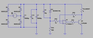
I thought about how I might go about doing that and came up with the attached concept.
Thoughts ?
I thought about how I might go about doing that and came up with the attached concept.
Thoughts ?
Attachments
For indirectly heated tubes, all you need is a quiet 6.3 V supply.
For directly heated tubes, there is much debate about whether one should use a current source or a voltage source for the filament supply. I've tried both and could not tell a difference neither in measurements nor in listening tests. So I developed a voltage regulator. My regulator has an output impedance on the order of 1~2 mOhm so it's about as close to an ideal voltage source as you can get. The schematic and boards are on my website if you're interested.
~Tom
Member
Joined 2009
Paid Member
If you adjust the current by measuring the voltage then you no longer have a high impedance supply; you have turned it into a low impedance supply.
The key here is not the d.c. impedance of the heater supply seen by the filament - it is best if it were low since a large current has to flow. Rather what is important is that there is a high impedance to a.c. across the two terminals of the heater supply. Does not my concept provide that - since the lower end of the filament 'looks' into a 1k resistor in parallel to the collector of a BJT ?
For directly heated tubes, there is much debate about whether one should use a current source or a voltage source for the filament supply. I've tried both and could not tell a difference neither in measurements nor in listening tests. [...]The schematic and boards are on my website if you're interested.
Thanks for the offer Tom. Did your current source have a high a.c. impedance across the heater ?
p.s. I'm talking DHT
Last edited:
Make floating voltage stabilizer with current limited right above it's nominal value, to limit inrush current. It's the best you can do. Then use one of leads as a cathode, anyway dynamic resistance between them will be low.
One more option is to shunt filament by 2 3.15V zeners (or shunt regulators) in series, and feed this thingy from floating current source.
One more option is to shunt filament by 2 3.15V zeners (or shunt regulators) in series, and feed this thingy from floating current source.
Member
Joined 2009
Paid Member
Yes, this is my plan, a floating supply. In my concept, the inrush is limited, in a subtle way. The op-amp drives the base of the power BJT through a resistor. By choosing a higher value resistor and/or specifying an op-amp with an appropriate output current limit, you have placed a cap on the current that can flow through the bipolar (limited by it's finite Hfe).
Zener's - this is a non-starter for too many reasons.
Zener's - this is a non-starter for too many reasons.
Thanks for the offer Tom. Did your current source have a high a.c. impedance across the heater ?
In order to provide a heater voltage that is constant across the audio band, I designed my regulator to provide low impedance across the audio band. I don't see a point of allowing the heater voltage to be modulated by the signal current. I'm talking about the output impedance of the regulator - i.e. the impedance the filament "sees" when "looking back into" the regulator. Not the impedance from input to output of the regulator which is quite high at RF.
Are you trying to design a regulator that acts as a voltage source at DC but as a current source from 1 mHz and up? Why? If you want a current source, design one. If you'd rather have a voltage source, build one of those... It's not clear from your post, but maybe you're looking for a current source with a voltage compliance no higher than, say 10 % above the nominal filament voltage. Is this correct?
~Tom
Last edited:
Member
Joined 2009
Paid Member
You already have Zener as reference.You may use TL431 and one transistor (well, couple of both) in series if don't like Zeners.
The problem with any kind of shunt regulator is that it is essentially a Class A device and will burn lots of juice - the filament is already hungry enough without adding to that. The other problem is that it offers an exceedingly low a.c. impedance across the filament - the opposite of what I want to achieve. I agree, the TL431 might be a good replacement as a voltage reference.
Are you trying to design a regulator that acts as a voltage source at DC but as a current source from 1 mHz and up? Why? If you want a current source, design one. If you'd rather have a voltage source, build one of those... It's not clear from your post, but maybe you're looking for a current source with a voltage compliance no higher than, say 10 % above the nominal filament voltage. Is this correct?
Yes, more or less you are right. Rod Coleman's filament supply provides a good guideline to the design goals - low d.c. impedance, high. a.c. impedance.
A pure current source is a possibility, but you have to include a sense resistor in series with the filament current. And people using Rod's current source have found that the sound is sensitive to the quality of this resistor. This resistor also dissipates wasted heat and increases the voltage headroom required for the filament supply. I'll give this some thought though.
Last edited:
The other problem is that it offers an exceedingly low a.c. impedance across the filament - the opposite of what I want to achieve.
Sorry, it was hard to imagine that you wanted it.
Member
Joined 2009
Paid Member
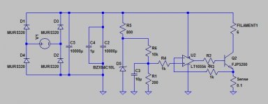
You don't need R3, R4. In fact, they may cause instability as they form a HF pole with the input cap of the op-amp.
The op-amp controls the base voltage on Q2 such that the voltage difference from the non-inverting to the inverting inputs of the op-amp become zero. Hence, the current in Q2 will be V(+)/Rsense.
~Tom
The op-amp controls the base voltage on Q2 such that the voltage difference from the non-inverting to the inverting inputs of the op-amp become zero. Hence, the current in Q2 will be V(+)/Rsense.
~Tom
Member
Joined 2009
Paid Member
Thanks Tom, I may play around with this concept a bit further. What I like is that the sense resistor can be of a low value, with less self-heating it will perform better and drop relatively little voltage. All made possible by the high gain of an op-amp. And who said you shouldn't use op-amps in hi end audio !
Thanks Tom, I may play around with this concept a bit further. What I like is that the sense resistor can be of a low value, with less self-heating it will perform better and drop relatively little voltage.
I like that about it as well. You will have to drop some voltage across Q2, however. One thought that has crossed my mind is to have a high-efficiency switcher up front. This switcher would deliver Vout = Vfilament + V(Q2) + V(Rsense). You'd probably have to drop some 500 mV across Q2. Still, with a 300B filament (my example) this would lead to 750 mW dissipated in Q2 and 225 mW dissipated in Rsense. That's pretty manageable.
You could also let the input voltage be unregulated - as in your example. Then you'd have to design for 500-ish mV across Q2 under worst case input voltage and ripple conditions and size the heat sink for the other worst case (high input voltage, low ripple).
All made possible by the high gain of an op-amp. And who said you shouldn't use op-amps in hi end audio !
Well... You only have control over the playback chain. Who says the recording chain hasn't had a few hundred op-amps in it?
") But that's a topic for another day.
But that's a topic for another day.~Tom
Member
Joined 2009
Paid Member
A regulator will cost voltage headroom and consequently more power dissipation. Given that we already have a current regulator I don't see a need for two, so maybe leave more headroom across the current regulator transistor instead - overall fewer parts. The bottom line is having lots of capacitance to minimize voltage ripple - and the associated need to be careful about the initial current demands when these caps charge up. I haven't looked into the use of some inductance yet.
Last edited:
Member
Joined 2009
Paid Member
A regulator will cost voltage headroom and consequently more power dissipation.
That's why I said "high efficiency". A switching supply doesn't dissipate much power and some switchers can boost the voltage so you can design around the headroom issues. But whatever floats your boat.
~Tom
Member
Joined 2009
Paid Member
- Status
- This old topic is closed. If you want to reopen this topic, contact a moderator using the "Report Post" button.
- Home
- Amplifiers
- Tubes / Valves
- dc filament heater - high impedance const. voltage