Hi
Same problem but in my case it is a simple grounded cathode preamplifier:
http://www.diyaudio.com/forums/tubes-valves/221181-voltage-divider.html
I tried this:
- good quality MC transformers in 13:1 mode
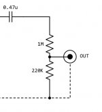
- voltage divider
Correct me if I am wrong but it should be a better solution with transformers ? very low output impedance ?
To my surprise, it's not better sounding, for information the preamp is connected to a small Trends TA10, 50K input.
If I connect the dac straight to the amp (preamp not used at all), I can't easily notice a difference - at least, to my ears -
I wonder if a not-so-low output impedance is not always a problem ?
if a voltage divider is not so bad ?
Thank you")
Same problem but in my case it is a simple grounded cathode preamplifier:
http://www.diyaudio.com/forums/tubes-valves/221181-voltage-divider.html
I tried this:
- good quality MC transformers in 13:1 mode
- voltage divider
Correct me if I am wrong but it should be a better solution with transformers ? very low output impedance ?
To my surprise, it's not better sounding, for information the preamp is connected to a small Trends TA10, 50K input.
If I connect the dac straight to the amp (preamp not used at all), I can't easily notice a difference - at least, to my ears -
I wonder if a not-so-low output impedance is not always a problem ?
if a voltage divider is not so bad ?
Thank you
Attachments
Thanks DF96.
I did this small test: sine wave tone generation from the computer, -3dB.
I can clearly hear until 16'000 Hz, preamp connected or not (dac straight to the amp).
How to explain this ? cable and amp have small input capacitance ?
May I ask you another question.. how does the output impedance is affected by the voltage divider ? like a transformer ?
I have an oscilloscope, time to learn how to use it
16kHz would only be attenuated by about -6dB so you would still hear it. Proves nothing. 100pF was a wild guess at capacitance to check the scope of the problem, but you are likely to be within a factor of 2 of that either way. 180k is far too high an output resistance.
The output resistance of a voltage divider, fed from a voltage source, is given by the parallel combination of the two resistors. 1M||220K is 180K. Very different from a transformer.
The output resistance of a voltage divider, fed from a voltage source, is given by the parallel combination of the two resistors. 1M||220K is 180K. Very different from a transformer.
Thanks again.
Removed the voltage divider, back to the 13:1 transformer, it's much better.
Sorry for the previous statement, I was wrong.
Although amplifying signal at input and decrease it at the output seems to be not very clever I guess.
I would like to estimate the output impedance. 6J7 plate resistor is 27K.
Output impedance about 27K / 4 = 6.75K ? with 13:1 transformer, 6.75K / 169 = 40 R ?
Approximation from this page:
Preamp Output Impedance Calculator
(6SN7 - 27K load with cathode bypass).
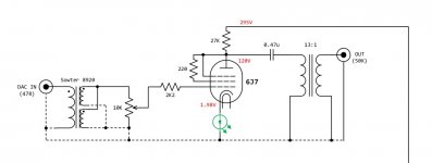
Here is a picture of the circuit.
edit: plate resistance is 27K
Preamp Output Impedance Calculator
(6SN7 - 27K load with cathode bypass).
Here is a picture of the circuit.
edit: plate resistance is 27K
Attachments
Impedance at the anode will be 27K in parallel with the anode/plate resistance (which is likely to be significantly smaller than 27K). The output impedance will then be this divided by 169.
Are you clear about the difference between plate resistor (a circuit component, 27k in this case) and plate resistance (a property of the valve/tube at a particular bias point)?
Are you clear about the difference between plate resistor (a circuit component, 27k in this case) and plate resistance (a property of the valve/tube at a particular bias point)?
Are you clear about the difference between plate resistor (a circuit component, 27k in this case) and plate resistance (a property of the valve/tube at a particular bias point)?
Sorry, misreading of your previous question
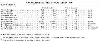
From the GE 6J7 datasheet, 10-11K plate internal resistance, maybe a little bit more in my case (because of lower plate voltage ? not clear). Around 50 ohms after the 13:1 step down transformer.
This preamp is actually not really needed, but later I would like to build an amp (I have a bunch of 6P6S and 6J7), 6J7 triode connected driving a PP or PPP.
Higher gain will be needed I guess.
Attachments
- Status
- This old topic is closed. If you want to reopen this topic, contact a moderator using the "Report Post" button.
- Home
- Amplifiers
- Tubes / Valves
- output attenuation