My preamp has too much gain, I know using a voltage divider at the input can solve, I need to reduce 6 or 12dBs, I think sources have 2V.
Using Z1 & Z2 1R I have an output voltage of 1V = -6dBs attenuation
Using Z1 1R & Z2 0R33 I have an output voltage of 0,5V = -12dBs attenuation
Are my calculations OK?
Using Z1 & Z2 1R I have an output voltage of 1V = -6dBs attenuation
Using Z1 1R & Z2 0R33 I have an output voltage of 0,5V = -12dBs attenuation
Are my calculations OK?
Hi,
Post details of your preamp, a far better solution may be very easy.
An attenuator on the pre-amps output is a very poor solution.
CD has max 2V, most other things less, sometimes all you need
is a CD attenuator built into the lead for the the CD, or similar.
rgds, sreten.
Post details of your preamp, a far better solution may be very easy.
An attenuator on the pre-amps output is a very poor solution.
CD has max 2V, most other things less, sometimes all you need
is a CD attenuator built into the lead for the the CD, or similar.
rgds, sreten.
The math is correct. However, you have to allow for the drive capability of the signal source. Modern, digital, sources can drive the IHF "standard" 10 KOhm load. The total of Z1 and Z2 should be at or slightly above 10 KOhms. The load should be 10X (or higher) Z2.
A good construction method for the divider is to place 1/8 W. 1% tolerance metal film resistors inside the RCA plugs, at the preamp end, of the interconnect cables.
A good construction method for the divider is to place 1/8 W. 1% tolerance metal film resistors inside the RCA plugs, at the preamp end, of the interconnect cables.
Note that Zload is in parallel with Z2, so if your load impedance is close to Z2, you have to take the loading into account to get your 6 dB of attenuation. As a rule of thumb, if Zload > Z2*10, the loading will be negligible.
In addition, as said by others already, you'll have to ensure that the total impedance of the voltage divider presents a reasonable load impedance to the preamp. With your circuit, you'll probably have to aim for Z1+Z2 > 10 kOhm. Perhaps higher.
A better way to go about this would - in my opinion - be to lower the gain of the preamp. 36 dB is a lot of gain...
~Tom
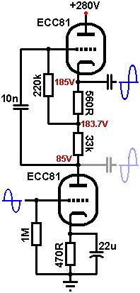
I agree with Tom that reducing the gain of the preamp would be a good idea, unfortunately I don't see anyway to do that easily without introducing other problems.
The usual method of reducing a triode gain stages gain by deleting the cathode bypass capacitor simply doesn't work for mu followers because the bootstrapped anode load impedance is so high that you have very little signal current swing and so don't develop significant signal voltage (feedback) across the cathode bias resistor, in fact I don't see why the cathode bypass cap is there at all.
FOR DISCUSSION ONLY: You may be able to introduce a feedback loop around the whole stage by adding a divider from after the output coupling cap back to the grid of the lower triode. This would make the lower triodes input grid become a virtual earth mixing point and then different gains for different inputs are easily accommodated by different series input resistors, that is, treat the entire mu-follower as if it were an inverting op-amp, not sure if this would give you something good or an oscillator, maybe someone who has actually tried it could venture an opinion.
Cheers,
Ian
- Status
- This old topic is closed. If you want to reopen this topic, contact a moderator using the "Report Post" button.
- Home
- Amplifiers
- Tubes / Valves
- voltage divider