Hi all.
I am a complete newbie at dealing with vacuum tubes, and my plan is to build a class A PP amp with c3g tubes for phase inverter and driver stage.
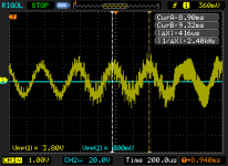
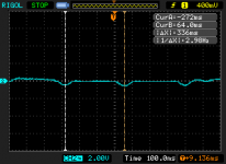
I have wired up three c3g tubes and been doing some tests. It seems to me like they are self oscillating. The oscilloscope screen shots shows the plate to GND voltage (oscilloscope in AC mode) of the PI stage. As you can see, there is an oscillation at about 400kHz, and I can not get rid of it.
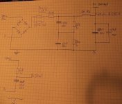
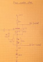
The setup looks pretty much like the drawings attached (sorry for the quality, I don't have a scanner), but I have tried some different grid leak resistors, grid series resistor etc. Also, the 100R resistor is not used.
In the c3g datasheet, there is no indication that I should use grid resistors for g2 and g3. Maybe I should? Could the lack of those be the cause of the oscillations?
I'm very thankful for all input.
Please feel free to ask for more info if needed.
I am a complete newbie at dealing with vacuum tubes, and my plan is to build a class A PP amp with c3g tubes for phase inverter and driver stage.
I have wired up three c3g tubes and been doing some tests. It seems to me like they are self oscillating. The oscilloscope screen shots shows the plate to GND voltage (oscilloscope in AC mode) of the PI stage. As you can see, there is an oscillation at about 400kHz, and I can not get rid of it.
The setup looks pretty much like the drawings attached (sorry for the quality, I don't have a scanner), but I have tried some different grid leak resistors, grid series resistor etc. Also, the 100R resistor is not used.
In the c3g datasheet, there is no indication that I should use grid resistors for g2 and g3. Maybe I should? Could the lack of those be the cause of the oscillations?
I'm very thankful for all input.
Please feel free to ask for more info if needed.
Attachments
Whether you need grid stopper resistors and if so, what value is difficult to predict as it depends on the wiring. The valve can for example act as a parasitic Colpitts oscillator, the tank being formed by the inductance of the grid wire, the grid to cathode capacitance of the valve and the capacitive load on the cathode side. If the wire connected to grid 2 is long, you might need a grid stopper on grid 2.
Is the phase inverter stage loaded by the output stages when you measure this oscillation? If so, is it stable when you disconnect the output stages? Do you use any overall feedback?
You wrote that you have tried grid series resistors on grid 1, but were they placed close to the grid? They get less effective when they are far away.
Hi
Maybe your input resistor 470k is working like feedback resistor.
And your input capacitor and input resistor 470k are rotating the phase of the signal.
It is possible to check my idea.
Please, change the value of the capacitor or of the input resistor and you will get oscillation on another frequency.
Let's see...
c3g as phase inverter... As I said, I'm a newbie. These seems like good tubes. Maybe they are not a good choice in a PI?
I have tried grid resistors of different values, but the oscillations stay. What's strange is that now when I started it all up after a trip to the supermarket, the oscillations are absent.
The PI stage was not loaded when I made the measurements. There is no global or local feedback. At least not intentional. I guess the quite high resistance (about 95 ohms) in the 10H coil could result in some kind of feedback?
The grid resistor is connected directly to the grid tab of the socket.
Actually, I have found one error. This issue with bad measurements has puzzled me for quite a while. The 400kHz signal comes from my secondary TFT monitor. My primary does not seem to be causing similar disturbances. What's strange about this is that hen the Oscilloscope (Rigol DS1052E) is just started and has not warmed up fully, these disturbances are not visible.
I am still having some stability issues though. Have to check further into this. I guess I'll come back with an update pretty soon...
What's strange is that now when I started it all up after a trip to the supermarket, the oscillations are absent.
have heard its a bit 'nervous' tube
I guess it means microphonic
but I also have some, so Im interested in how best to use them
The stability issues I'm experiencing right now are like this:
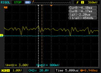
The B+ voltage swings about +- a couple of volts (max) at a frequency of 3 Hz. The swing does not really form a sinus curve, but rather a quite straight (horizontal) line with dips every 330ms.
This swing is clearly caused by the circuit (forget everything I said before about mains voltage - I must have been tired when I came to that conclusion...).
Attachments
I don't see any grid stopper resistors in your schematic, with the C3G and other high transconductance pentodes it is a very good idea to install a series resistor at the screen (G2) and control grid (G1) of the tube. (Not needed on G3.) I'd recommend something like 1K, and install them right on the socket.
I know you have eliminated the 400kHz issue as being the result of a noisy monitor, but you may have HF/VHF oscillations that you cannot see with moderate bandwidth scopes, sometimes there will be other manifestations though. Snooping with an AM/FM portable radio may help to identify if the driver stages are oscillating.
I don't see a problem with using the C3G as a phase inverter in triode connection, or as part of a QUAD II style amplifier implementation if you have an appropriate OPT.. One thing I would say though is that your plate and cathode resistors should be roughly twice the values shown minimum for good linearity with the C3G.. Interesting adjustable bias scheme, I would however restrict the bias range so that you always have at least -1V of bias no matter what the pot setting.
The C3G has a reputation for filament fragility so I would let them cool for a couple of minutes before removal. I'm not sure they are any more microphonic than other similar types. I have a few and almost used some in my latest dac project, but they take up too much space.
Wouldn't the 470k resistor be the grid stopper, or have I misunderstood something?
I have tried different resistors in series with g1 but they are not in the drawing. Maybe a 1k resistor at g2 would be a good idea.
Regarding the load resistors, I kind of went with the recommended values from the Siemens c3g data sheet. Maybe higher values would be a good idea. I though the voltage drop over the resistors would be a bit low with the current values.
I'm not sure I understand that about "filament fragility" and "cool for a couple of minutes before removal".
Regarding the bias setup; I just thought I'd try something I had not seen yet. Don't know if this is better than any other solution, but LED biasing seems quite popular and the pot gives me the ability to adjust the bias voltage.
I'm not sure I understand that about "filament fragility" and "cool for a couple of minutes before removal".
meaning it does not like to be shaken(or sturred), especially when on and hot, and that its best to handle carefully, in general, I suppose
or in other words, not the best tube for a road touring guitar amp

Aah, I get it. Luckily, I plan to have mine stationary in the living room
I have now promised myself I should not do any more work this evening, but I came to some interesting conclusions before I finished up.
Have a look at the schematics for the PSU (first post). The voltage drop seems to occur over the two 22 ohm resistors in parallel. The drop is about 500mV, and if I measure after the 10H inductor, the drop is of equal size.
The drop could only be caused by a sudden change in load, and since the drop is of equal size before and after the inductor (95 ohms) I guess the only thing that could cause this is the two capacitors in series?!
The capacitors are these and the resistors in parallel with those are 3w wire wound. The 22 ohm resistors are also wire wound.
C3g, C3m, C3o are low noise (German post) telecom (long distance telephone transmission, cable repeaters -under the ocean-) tubes. C3g inner -cathode- structure mostly similar than old direct heated triodes, therefore very fragile, when hot or warm. Be patient, wait few minutes before move it.
C3g is the least of microphonic tube, but some of them produce a little noise about four-six kilohertz narrow spectrum.
They are very linear tubes, my collection (few dozen) produce 0.33-0.86 % THD at 240Vpp!
But... likes power, below 20mA THD is higher than ordinary.
Nlinus, I think, this configuration is underestimated, max. swing only 100Vpp, and THD is a bit high (simulation: 0.85% at 92Vpp).
Last edited:
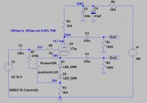
Yes, you've misunderstood something.. The 470K is the grid (bias) resistor, the grid stopper appears in series between the grid and everything else that is external. The grid stopper effectively reduces the Q of external wiring inductance and provides isolation between that and the grid's stray and miller capacitance, it also creates an HF pole which can be intentionally chosen to roll off HF gain above a certain frequency to reduce susceptibility to external RFI in an input stage as an example.
The 470K is the grid (bias) resistor, the grid stopper appears in series between the grid and everything else that is external. The grid stopper effectively reduces the Q of external wiring inductance and provides isolation between that and the grid's stray and miller capacitance, it also creates an HF pole which can be intentionally chosen to roll off HF gain above a certain frequency to reduce susceptibility to external RFI in an input stage as an example.Well then...
I must have gotten the terminology wrong. Anyway, I have a grid stopper resistor connected directly at the tube.
The voltage fluctuations is driving me nuts. Could it maybe be caused by mechanical movement/vibrations in the transformer? Or bad capacitors (although they are brand new)? Well, I'll continue with this tomorrow...
Not quite sure where you are in terms of the build. I assume you have not closed the feedback loop so far and those blips every 330ms on the supply rail aren't because the amplifier has a subsonic oscillation which it very well could. Open global feedback loop if present if this has no effect then try removing one tube (input tube) and see if the blips go away - if they do then it is feedback through the supply and you will need to revise the design to provide more decoupling between the various amplifier stages..
Also at this point it seems worthwhile if you could post a schematic of the entire amplifier.. Snapshots of your notebook pages will be just fine for this purpose.
Also at this point it seems worthwhile if you could post a schematic of the entire amplifier.. Snapshots of your notebook pages will be just fine for this purpose.
Actually only the PI and driver stages are wired, but this phenomenon appears even with all three tubes removed from their sockets.
As I mentioned earlier: The voltage drops are of equal magnitude before and after the inductor - which causes me to believe that the cause of these drops should be located before it. Have to check more tomorrow...
The transformer and inductor are made by a Polish company named Indel. I bought them here (the inductor is here). These are very cheap in comparison to other brands, but I thought I'd try. Right now, I'm not really sure if these could have something to do with my issues :s
- Status
- This old topic is closed. If you want to reopen this topic, contact a moderator using the "Report Post" button.
- Home
- Amplifiers
- Tubes / Valves
- c3g self oscillation problem - a newbie needs help!