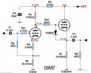
Usually when DC coupling a common cathode and a cathode follower, a technique that connects the grid and the cathode of the cathode follwer valve with a semiconductor diode will be used, as the picture shows. It is used to prevent extrem large current through the cathode follower when negative grid voltage is to be established during the power-up. This diode will be reversely biased after the negative grid voltage buids up and then cut off.
However, I have a question here. As it apprears between the grid and the cathode of the cathode follower valve, will it be part of the input impedance of such valve. And more worsely, as the diode has very small impedance when being forwardly connected while very large impededance when being revsersely connected. Will this make the input impedance of the cathod follower rather unstable with regard to AC signal between the grid and the cathode?
Hope somebody can help to carify it. Thks.
Attachments
Seems the publisher of that circuit is pulling the good tube peoples' legs here Kenneth.
Or, could it be the operating point has changed?
Or, could it be the operating point has changed?
An externally hosted image should be here but it was not working when we last tested it.
Last edited:
The capacitance of the diode will vary with signal, but it is bootstrapped by the cathode follower. For an ECC83/12AX7 it will see very little signal voltage. I have used a diode like that for an ECC83 LTP phase splitter, where one might expect greater signal voltage combined with much less bootstrapping, without any harm. However, I used a 1N4148 which has much less capacitance than a 1N4007. Just use any small-signal low capacitance silicon diode, not a rectifier.
Call me what you will, but I have never used one of these diodes, I do use neon lamps and diodes for cathode clamping on LTP running on high voltage negative rails.
I've never had or seen a tube fail in an application where the modern trend seems to be to use that diode. I will admit I often, but not always use tube based supplies that warm up moderately slowly. (Regulators with a series pass tube or tube rectifier with an indirectly heated cathode)
I'd say if you must use a diode that the 1N4148 or 1N914 would be better choices.
Call me what you will, but I never had problems with directly coupled tubes without any diodes: for example, if anode load resistor in the previous stage can provide too high grid current I better add in series with the grid something like 56k resistor with 100 pf cap in parallel with it, like I did in my Pyramid amp (schematic available in several topics).
The use of the diode was made popular by John Broskie. Its purpose is mainly to protect the second tube if the first tube loses conduction (pulled from socket or shook loose etc.) in an already hot amplifier. A little redundant if using a double triode like in the op schematic. The need for it to deal with warmup issues would only be when using a current source load on the first triode since just a resistive load would self balance if the grid began to draw current the resistor would then begin to drop voltage and reduce current where a ccs would let the grid reach the full available current before it began dropping voltage.

I'm not convinced it is a "dunsel" but then I'm not convinced it is'nt either!!!! (fence sitters unite - yah!)
If you are at all concerned about the capacitance of the diode then use 1N914, 1N4148 etc. small signal diode in preference to power diodes (*as suggested above) and for serious paranoia use 2 or 3 of them in series to divide the total capacitance.
Cheers,
Ian
If you are at all concerned about the capacitance of the diode then use 1N914, 1N4148 etc. small signal diode in preference to power diodes (*as suggested above) and for serious paranoia use 2 or 3 of them in series to divide the total capacitance.
Cheers,
Ian
That could be less successful than you might expect, as the reduced reverse voltage across each diode would increase its capacitance so the net capacitance would not reduce by so much.gingertube said:for serious paranoia use 2 or 3 of them in series to divide the total capacitance.
Whether this diode/neon is needed could depend on what the valve is. A high gain valve with fine grid very near the cathode (e.g. ECC83, ECC88) is more likely to benefit from it than a low gain valve with a coarser grid further away from the cathode (e.g. ECC82, 6CG7).
How about using a sting of LEDs under the cathode. Follows the same practise I'd guess?
The use of the diode was made popular by John Broskie. Its purpose is mainly to protect the second tube if the first tube loses conduction (pulled from socket or shook loose etc.) in an already hot amplifier. A little redundant if using a double triode like in the op schematic.
No, the diode protects against start up too, when the cathodes are still cold and therefore the grid of the CF is pulled up to the supply voltage while the cathode is still stuck at ground. I have killed a few valves this way! (arcing between grid and cathode). This is not just a Broskie technique- it's been around for decades in analog computers.
- Status
- This old topic is closed. If you want to reopen this topic, contact a moderator using the "Report Post" button.
- Home
- Amplifiers
- Tubes / Valves
- Will this arrangement impact the input impedence of the cathode follower?