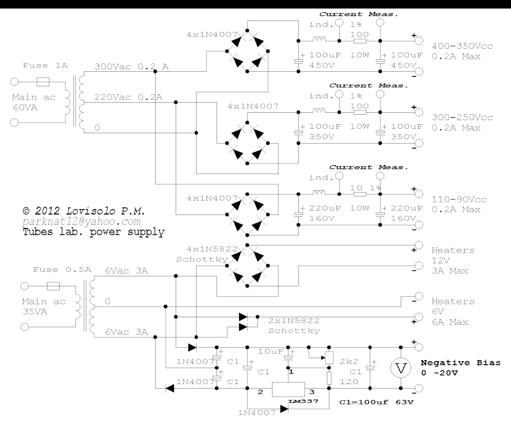
This is my project, based on low cost and semplicity.
It has three HT voltages, two heater voltages (not filtered) and stabilized negative bias voltage regulator 0 -20V (LM337).
NOTE: the HT outputs cannot be tied togheter!
If more than one HT voltage are required on same circuit (same ground), three separate transformer winding are required (110/220/300Vac).
The two heaters voltages are just rectified but not filtered with any caps, effective voltage should not change for heaters (same power dissipated).
Inductors are iron core > 2H
HT output voltages depend on current, additional output series resistors may be added to get desired voltage.
NOTE: 1% resistors act like a "shunt" for measuring supply currents (measuring voltage drop) and also limiting peak currents.
 HIGH VOLTAGE. DANGER!
It has three HT voltages, two heater voltages (not filtered) and stabilized negative bias voltage regulator 0 -20V (LM337).
NOTE: the HT outputs cannot be tied togheter!
If more than one HT voltage are required on same circuit (same ground), three separate transformer winding are required (110/220/300Vac).
The two heaters voltages are just rectified but not filtered with any caps, effective voltage should not change for heaters (same power dissipated).

Inductors are iron core > 2H
HT output voltages depend on current, additional output series resistors may be added to get desired voltage.
NOTE: 1% resistors act like a "shunt" for measuring supply currents (measuring voltage drop) and also limiting peak currents.
Last edited:
My no good advise is:
A series regulator or a variac is simpler, only one circuit and no chance someone tries to use the different taps at the same time.
For bias supply i would prefer a separate winding.
For bias stack a couple of multiturn pots as voltage dividers, with unregulated ht you want unregulated bias.
Have 2 separate 6v heaters that you can series for 12v.
A series regulator or a variac is simpler, only one circuit and no chance someone tries to use the different taps at the same time.
Variac and series regulator (if variable) are both too expensive
For bias supply i would prefer a separate winding.
Extra cost, unnecessary")
For bias stack a couple of multiturn pots as voltage dividers, with unregulated ht you want unregulated bias.
Circuit with LM337 is cheaper than a couple of multiturn pots.
Also, stabilized voltage is always better than unregulated.
Have 2 separate 6v heaters that you can series for 12V
Extra cost, unnecessary
Variac and series regulator (if variable) are both too expensive
For bias supply i would prefer a separate winding.
Extra cost, unnecessary
For bias stack a couple of multiturn pots as voltage dividers, with unregulated ht you want unregulated bias.
Circuit with LM337 is cheaper than a couple of multiturn pots.
Also, stabilized voltage is always better than unregulated
.Have 2 separate 6v heaters that you can series for 12V
Extra cost, unnecessary
Last edited:
You are full wave rectifying 6.3 and 12.6 V for your 6 and 12V supplies. They will be too high for tubes as the 6.3V will be closer to 9V and the 12.6V will be close to 18V!
This will blow heaters.
You will short diodes in your HV supplies IF you tie them together for a common ground.
This will blow heaters.
You will short diodes in your HV supplies IF you tie them together for a common ground.
You are full wave rectifying 6.3 and 12.6 V for your 6 and 12V supplies. They will be too high for tubes as the 6.3V will be closer to 9V and the 12.6V will be close to 18V!
This will blow heaters.
I did not use filter capacitors after rectifiers, effective voltage should not change for heaters (same power dissipated).
You will short diodes in your HV supplies when you tie them together for a common ground.
The three outputs are not designed to be tied togheter, sorry I forgot to mention this advice (added). Good point!
Last edited:
A series regulator or a variac is simpler, only one circuit and no chance someone tries to use the different taps at the same time.
Variac and series regulator (if variable) are both too expensive
For bias supply i would prefer a separate winding.
Extra cost, unnecessary
For bias stack a couple of multiturn pots as voltage dividers, with unregulated ht you want unregulated bias.
Circuit with LM337 is cheaper than a couple of multiturn pots.
Also, stabilized voltage is always better than unregulated
Have 2 separate 6v heaters that you can series for 12V
Extra cost, unnecessary
Ok a series regulator will cost a few $ more but you need only one bridge and one set of caps.
A switch to choose the 220 or 300 winding not to burn of to much power in the reg.
I even think the caps cost more then the sand in the reg ?
If you go for unregulated HT don´t regulate the bias, that way they drift equally when mains drift.
What´s the differencce in cost for using you 2 windings as separate 6v instead of one 6 and one 12 ?
Keep heater AC for general purpose and add a small bridge and a 7806 with a couple of diodes to ground for "pre/phono" use.
I did not use filter capacitors after rectifiers, effective voltage should not change for heaters (same power dissipated)
Then why rectify at all ? it just makes more noise
If you go for unregulated HT don´t regulate the bias, that way they drift equally when mains drift.
This is just a cheap and easy lab power supply for testing tubes and repairing amps, for these purposes it is enough.
Most of the components, including Shottky diodes and HT caps (to be tied together if voltages are not enough), can be recovered frorm an old computer's power supply.
If you need a precision and low noise power supply, to make THD or noise measurements, this project is not what you want.
Last edited:
looks like the power supply to an amp I was involved in trouble shooting today.
as far as your circut goes...I like the concept....recommendations would be more options on bias voltages.
Plate Voltages 325, 400 VDC
Bias Voltages -60, -48, -36, -24, -14 VDC
Filament Voltage 6.3 VAC
Filament Current 6 Amps maximum filament current
Measurement Functions Plate Current (Ip) Range: 0 to 120.0 mA DC, ± 1.5 %
Attachments
You need to be extremely careful when you use this power supply because you are deriving dc HT output voltages from different taps of the same secondary windings. Although you bring out a separate 0V for each HT voltage, you must never connect any of these 0Vs together because that would lead to one winding of the transformer secondary being shorted via the bridge rectifiers.
Cheers
Ian
Cheers
Ian
- Status
- This old topic is closed. If you want to reopen this topic, contact a moderator using the "Report Post" button.
- Home
- Design & Build
- Equipment & Tools
- Lab power supply for testing tubes