I need a B+ of approx 150v
I have several possible rectifiers, but have narrowed the field to either a 5Z3 or a 6X5WGT as I have a few of each. I also like the big 5Z3 just for looks.
I am a bit of a noob to designing supplies, and am trying to work my way through all the formula and postings on reverse engineering the voltage to assess the ACV from the transformer.
If I use a specific tube, I know it's volts drop from the data sheet, and I know I will lose about 20v through a choke, so I can factor those it. I also read that I will get a DCV about 1.41 times the ACV.
So assuming a 5Z3 with a volts drop of 58v at full load and a 8/10h choke losing another 20v, I figure I need a PT of around 165-0-165
Am I doing this correctly?
I realize that the rectifier won't be at full load, so I need to compensate those volts drop a bit. Average load will be 50ma.
TIA
I know about it
") Two issues:
Two issues:It won't work on a MAC (although I can workaround that)
It doesn't help me learn how to work it out myself (without a degree in maths)
I'm first to admit I'm not an expert ... but with a full wave choke input (I'm assuming that is what you're using from your comments) you're not going to get DC at 1.41 times the AC.
Check: http://www.hammondmfg.com/pdf/5c007.pdf
Check: http://www.hammondmfg.com/pdf/5c007.pdf
Are you planning on using a cap input or choke input supply?
Choke input supplies require a rather beefy choke compared to a cap input supply.
Do you know the DCR of your intended choke? The DCR of the transformer secondary is also helpful.
As you already determined, the voltage drop across the rectifier tube is a function of current as well.
A capacitor input (CLC or CRC) supply is going to give you roughly 1.41 x transformer secondary (less voltage drop for various series resistance at your current draw, including the drop for the resistance of the choke).
A choke input supply is going to give you roughly .9 x transformer secondary V less the voltage drop across your series R at your required current draw.
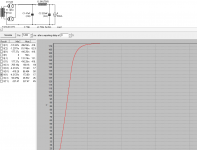
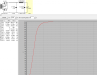
PSUDII is your friend here. Not only will it give you the resulting B+, but it will warn you if your first cap is too large for your rectifier (not an issue with SS rectification), how much ripple you'll end up with, and loads of other stuff as well.
If you do a CLC supply, you can lower your B+ by either reducing the value of C1 below about 8uf or so, way down to less than 1uf, or just add series resistance. Both of these things can be easily modeled in PSUD. Adding series R helps reduce ripple but increases your power supply output impedance.
The images below show the effect of changing the choke R and transformer secondary R on B+.
Choke input supplies require a rather beefy choke compared to a cap input supply.
Do you know the DCR of your intended choke? The DCR of the transformer secondary is also helpful.
As you already determined, the voltage drop across the rectifier tube is a function of current as well.
A capacitor input (CLC or CRC) supply is going to give you roughly 1.41 x transformer secondary (less voltage drop for various series resistance at your current draw, including the drop for the resistance of the choke).
A choke input supply is going to give you roughly .9 x transformer secondary V less the voltage drop across your series R at your required current draw.
PSUDII is your friend here. Not only will it give you the resulting B+, but it will warn you if your first cap is too large for your rectifier (not an issue with SS rectification), how much ripple you'll end up with, and loads of other stuff as well.
If you do a CLC supply, you can lower your B+ by either reducing the value of C1 below about 8uf or so, way down to less than 1uf, or just add series resistance. Both of these things can be easily modeled in PSUD. Adding series R helps reduce ripple but increases your power supply output impedance.
The images below show the effect of changing the choke R and transformer secondary R on B+.
Attachments
Last edited:
I know about it
It won't work on a MAC (although I can workaround that)
It doesn't help me learn how to work it out myself (without a degree in maths)
Well, if you want to get proper values, you will need some math. Here we go: http://techpreservation.dyndns.org/beitman/abpr/newfiles/Rectifier Analysis Part 1.pdf
Being a physicist, I know it's nice to works things out for yourself, but the time and frustration you would have to spend here is not worth it. Stupid calc. of nasty integrals and so on. Figure out what's going in such a PSU and after that, use the software.
I just read, well no I just looked at that PDF. I almost burned my eyes on the equations!
- Status
- This old topic is closed. If you want to reopen this topic, contact a moderator using the "Report Post" button.
- Home
- Amplifiers
- Tubes / Valves
- Some Power Supply Help