Here is the second test. This is with the GZ34, R16=4.7K, All tubes in and no signal applied.
R7=2.2K
R8=270K
R9=R14=150k
Voltages
HV1=348
HV2=347
HV3=343
BIAS=23.3
R7=1.45
R8=215
R9=125
R14=126
Clipping at 9.1VRMS into 8ohm load. Possibly a tick better then the previous test. A bit over 10 watts.
The numbers you calculated for the VP and VK of the input look to be about what you have in your last calculation. Numbers seem to work, might be the best that can be had with the design. I'm going to drill out a test chassis to mount all the mess up the plug into a speaker to see what it sounds like.
Sandy
I have a question. When you report the voltage...
R8=215
...does that mean there are 215V dropped across R8? If so, is the voltage at the plate of the first stage 6SL7 = +128V?
Thanks.
--
I looked at the GE datatsheet for 6V6GTA, and for a single 6V6 in class A, with a plate voltage of +315V and a screen voltage of +225V, you're supposed to get 5.5W output at 12% THD. I don't think it's unreasonable to expect only 10W from a push-pull pair of 6V6GT in class A, especially if used ultralinear (screen taps on the OPT).
Last edited:
Numbers seem to work, might be the best that can be had with the design.
How do you know that for sure? That's what I'm trying to figure out.
Can you tell us what is the voltage at the first stage 6SL7 plate?
Can you tell us what is the voltage at the second stage 6SL7 cathode?
Just those two voltages, nothing else, please. Those are two very important voltages.
--
Rongon -
Made a couple of posts yesterday night to reply, but not sure why they didn't show and oddly got notified again of your last post. Not sure what happend, but I'll try to remember what I wrote...
First off, I forgot to include the plate voltage in the early measurements. I'll repost the last 2 results with those numbers.
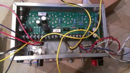
To be clear on what the numbers are HV1,HV2, HV2, Bias, V1PA, V1PB are measured at the check points on the schematic. The important ones that I forgot to included were V1PA (Input Plate), V1PB (Phase Inverter Plate), I had them measured, but for some reason skipped putting them down in the post!
The rest of the resistors are measured across the resistor showing the drop.
R14 will show the phase inverters Cathode voltage as this resistor is from cathode to ground in this case.
TEST 1
R7=1.2K
R8=220K
R9=R14=150k
Voltages
HV1=346
HV2=345
HV3=339
BIAS=23.1
V1PA=112
V1PB=224
R7=1.1
R8=224
R9=113.7
R14=114.9
TEST 2
R7=2.2K
R8=270K
R9=R14=150k
Voltages
HV1=348
HV2=347
HV3=343
BIAS=23.3
V1PA=124
V1PB=217
R7=1.45
R8=215
R9=125
R14=126
Let's hope I copy&pasted better this time...
Sandy
Made a couple of posts yesterday night to reply, but not sure why they didn't show and oddly got notified again of your last post. Not sure what happend, but I'll try to remember what I wrote...
First off, I forgot to include the plate voltage in the early measurements. I'll repost the last 2 results with those numbers.
To be clear on what the numbers are HV1,HV2, HV2, Bias, V1PA, V1PB are measured at the check points on the schematic. The important ones that I forgot to included were V1PA (Input Plate), V1PB (Phase Inverter Plate), I had them measured, but for some reason skipped putting them down in the post!
The rest of the resistors are measured across the resistor showing the drop.
R14 will show the phase inverters Cathode voltage as this resistor is from cathode to ground in this case.
TEST 1
R7=1.2K
R8=220K
R9=R14=150k
Voltages
HV1=346
HV2=345
HV3=339
BIAS=23.1
V1PA=112
V1PB=224
R7=1.1
R8=224
R9=113.7
R14=114.9
TEST 2
R7=2.2K
R8=270K
R9=R14=150k
Voltages
HV1=348
HV2=347
HV3=343
BIAS=23.3
V1PA=124
V1PB=217
R7=1.45
R8=215
R9=125
R14=126
Let's hope I copy&pasted better this time...
Sandy

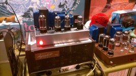
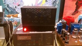
A shot of the EZ10 testing. With only one amp hard to give it a thorough testing, but I swapped out one of the EZ260 Grommes amps with the 10watt version and it sounds very clean and quiet. Less punch, but that's to be expected.
I have since taken it to my office and where I have one of those Chinese SET KT88 headphone amps (Noisy, hummy, cheep) and swapped out one channel and it sound very good, possibly a bit more punch. This is running a smaller speaker (polk audio) and smaller room where I intend to use it so just need to get the second set of transformers from EDCOR and build the second channel.
I also swapped out the GZ34 with a 5U4GB to see if I could hear anything but seemed similar, but hard to tell with only one channel. Will be trying this test again just to see if I can hear a difference.
I think the mini-monoblocks will work out nice for my computer audio system.
One thing to note is the gain is bit lower then the other amps I have, but doesn't seem to be a problem with what I'm driving it with. Some of the changes in the design may also have reduced gain a bit, but really don't think it makes a huge difference when all said and done.
Again want to thank everyone that chimed in with suggestions and help!!!!
Will post the completed amps once I get the transformers and chassis painted all up.
Sandy
Attachments
Sounds good!
Re: Lower gain -- Vintage amps had too much gain for today's sources. A computer sound card can usually send 1Vrms signal. CD players are supposed to send 2Vrms (2.83V peak) audio signal output. So the amp should be able to accept 1.5V to 2V peak signal at its input without clipping (leaves a little headroom for weak sources). Most vintage amps would clip with as little as 0.5V peak signal at the input.
Also, if you're using a log-taper, carbon-track potentiometer as your volume control, it will usually sound better if that control is turned up to 10 o'clock to 2 o'clock or so for normal listening, instead of down at around 8 o'clock.
As long as the amp reaches full output with the vol control turned up nearly all the way, then you're fine. I see no point in having a system where turning it up half-way causes clipping.
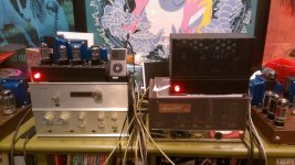
Is that Stereo 70 working? It looks like it's been modded. How does your EZ10 sound in comparison to that?
--
Re: Lower gain -- Vintage amps had too much gain for today's sources. A computer sound card can usually send 1Vrms signal. CD players are supposed to send 2Vrms (2.83V peak) audio signal output. So the amp should be able to accept 1.5V to 2V peak signal at its input without clipping (leaves a little headroom for weak sources). Most vintage amps would clip with as little as 0.5V peak signal at the input.
Also, if you're using a log-taper, carbon-track potentiometer as your volume control, it will usually sound better if that control is turned up to 10 o'clock to 2 o'clock or so for normal listening, instead of down at around 8 o'clock.
As long as the amp reaches full output with the vol control turned up nearly all the way, then you're fine. I see no point in having a system where turning it up half-way causes clipping.
Is that Stereo 70 working? It looks like it's been modded. How does your EZ10 sound in comparison to that?
--
Sounds good!
Re: Lower gain -- Vintage amps had too much gain for today's sources. A computer sound card can usually send 1Vrms signal. CD players are supposed to send 2Vrms (2.83V peak) audio signal output. So the amp should be able to accept 1.5V to 2V peak signal at its input without clipping (leaves a little headroom for weak sources). Most vintage amps would clip with as little as 0.5V peak signal at the input.
Also, if you're using a log-taper, carbon-track potentiometer as your volume control, it will usually sound better if that control is turned up to 10 o'clock to 2 o'clock or so for normal listening, instead of down at around 8 o'clock.
As long as the amp reaches full output with the vol control turned up nearly all the way, then you're fine. I see no point in having a system where turning it up half-way causes clipping.
Is that Stereo 70 working? It looks like it's been modded. How does your EZ10 sound in comparison to that?
--
The Stereo 70 is not an original
") It's a Bob Latino ST70 with a few of his upgrades. It's a very clean sounding and I want to say FAST and sensitive amplifier if that has any meaning in how to describe the sound. I also have a pair of modified Dynaco MKIII with the Triode Electronics Driver boards that I restored. And my favorite sounding is the Grommes 260A Clones (EZ260). They had the worst waveforms, but sound the best to me. I would rate them in how I enjoy the way they sound as EZ260, ST70, MKIII's. The ST70 that Bob Latino does is a great amp, very powerful, and it's really what got me going on the tube thing. I have to work on a pre-amp, the stock PAS-2 that I have is very tired. I have one of his PAS-2 upgrades, just have not got to finishing it it yet.
It's a Bob Latino ST70 with a few of his upgrades. It's a very clean sounding and I want to say FAST and sensitive amplifier if that has any meaning in how to describe the sound. I also have a pair of modified Dynaco MKIII with the Triode Electronics Driver boards that I restored. And my favorite sounding is the Grommes 260A Clones (EZ260). They had the worst waveforms, but sound the best to me. I would rate them in how I enjoy the way they sound as EZ260, ST70, MKIII's. The ST70 that Bob Latino does is a great amp, very powerful, and it's really what got me going on the tube thing. I have to work on a pre-amp, the stock PAS-2 that I have is very tired. I have one of his PAS-2 upgrades, just have not got to finishing it it yet. The funny thing was the EZ10 was going to be used as a simple amplifier for some of my transistorized HAM gear to get some of the old tube sound that I enjoyed, who knew it would sound so good
I think I have one more power amp in me, the EZ10 was a better project to learn some things (I think I could do a load line now!). Will be getting back to the EZ125 wth 6SN7's and 4 Kt88 as time permits...
Sandy
Re: Dyna PAS2 - If it's even close to stock, then you can do much better, and pretty easily too.
Do you spin vinyl, or are you all-digital for your source material? The only signal source that really needs its own dedicated preamp is a record player.
If you're all-digital, then you don't even need a line stage with gain. The lowest distortion preamp is no preamp at all. All the amps you have can likely be driven to clipping with the 2.83V peak out from a CD player (your EZ10 can). If your interconnect cables are no longer than about 6 feet or so, you might consider putting together a box with the necessary input and output jacks, a high quality input selector switch and a high quality stepped attenuator. You could even use an "inductive attenuator" like those from Intact Audio.
--
Source is mostly digital, but call me crazy I like tone controls. I'm not a fancy purist or anything like that, so for me I'm ok with the added 'color' a preamp has. I have a couple of un-built Glassware Akido preamp boards and that is also in the works, but I have a nice Dynaco PAS-2 project with upgraded preamp board (Tubes4Hifi) BUT retaining the tone controls.
I think of it this way, it's my music I'll make it sound the way I like to listen to it and if I have a bad mix I can turn a knob and make it enjoyable even if not accurate
Sandy
I think of it this way, it's my music I'll make it sound the way I like to listen to it and if I have a bad mix I can turn a knob and make it enjoyable even if not accurate
Sandy
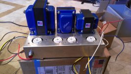
Finally finished the paint on the chassis and covers. They are painted Textured black very similar to the old Dynaco brown texture on the ST70 and MKIII's.
Paint was off the shelf etching primer with a first coat of satin black, then the texture coat (I forget the exact name on the can). The finish is very nice, better then I had hoped for.
Tubes are Sylvania JAN6SL7GT's Tungsol 6v6's (reissue) and JJ GZ34
One last change to the parts was done as I found the initial BIAS for the 6V6's were just too high. They were showing 34ma at about 350v at the each tube with the 270 ohm bias resistor (Tested with a bias tap), I changed it to a 400ohm (2x200 5 watt in series). It came down to about 28/29ma which is still a bit high but hopefully more in range. I don't like cathode bias resistor set up, seems a problem chasing the settings and I'll likely use a regular negative supply, but sounds good and was a simpler circuit.
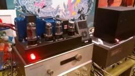
I swapped speaker leads and played them into my Polk Audio SRS speakers and was blown away how solid these little amps sound. They lack the punch that their bigger brothers have which is to be expected. Very clear top end and solid bottom end.
Happy New Years!
Paint was off the shelf etching primer with a first coat of satin black, then the texture coat (I forget the exact name on the can). The finish is very nice, better then I had hoped for.
Tubes are Sylvania JAN6SL7GT's Tungsol 6v6's (reissue) and JJ GZ34
One last change to the parts was done as I found the initial BIAS for the 6V6's were just too high. They were showing 34ma at about 350v at the each tube with the 270 ohm bias resistor (Tested with a bias tap), I changed it to a 400ohm (2x200 5 watt in series). It came down to about 28/29ma which is still a bit high but hopefully more in range. I don't like cathode bias resistor set up, seems a problem chasing the settings and I'll likely use a regular negative supply, but sounds good and was a simpler circuit.
I swapped speaker leads and played them into my Polk Audio SRS speakers and was blown away how solid these little amps sound. They lack the punch that their bigger brothers have which is to be expected. Very clear top end and solid bottom end.
Happy New Years!
Attachments
Don't know how they compare to the old Tungsols as I only have a set of the new ones and a set of JJ's. I can say that I ran these for about 10 hrs with 350v on the plates and about 35ma on each tube. The bias was set way too high and I just reduced it with a change to the cathode resistor down to about 29ma which is still a bit hot, but no red plates, not yet. They are not terribly expensive for a set, and if and when these go bad I'll try the JJ 6V6 that I also have.
I think these amps would be good for a guitar amp too, as they break up really nice when pushed beyond their limit, oddly still sounds good when you can hear vocals start breaking up on some music I was playing with.
The amp has a good low end punch, it's little but seems to have a bit more bottom end then expected, not sure if that is charistic of the 6V6's in this circuit but it works out really well with the smaller Polk Audio bookshelf speakers I have on my computer.
Sandy
if those tungsols go south the JJs will handle it rated max at 500v and I had 4 run at 420v usually about 20-23ma but for like straight month I cranked up that bias pot all the was and was drawing like 30-32ma them suckers don't budge lol they kinda have sterile highs though but the low end is massive mine lasted about 2 years before rattle issues figures lol
- Status
- This old topic is closed. If you want to reopen this topic, contact a moderator using the "Report Post" button.
- Home
- Amplifiers
- Tubes / Valves
- New 6V6 Build - Suggestions Needed