Rongon -
The voltages measured were with all tubes installed, shorted input and an 8ohm load on the output. Sorry wasn't clear on how I called it out.
I changed the 270k plate resistor to a 150k, but I don't think made a difference on the quick test in the clipping department, but didn't have a bunch of time to really check things out.
I will give figuring out the load line in the chart and see how it works, which I'm guessing will yeild a different value of resistors for the phase inverter.
One thing that confuses me is where you use the where you mention plate voltage, and just to be sure that is the voltage measured at the plate of the tube after the dropping resistor or before for use in creating the new load line?
Go easy on me if these seem rudimentary questions
Pointy - I think I have a few other issues before looking at the filiment, I think my first guess parts selection are way off for setting up the operating points of the tube.
Sandy
@SandyG
Plate voltage is measured right on the plates of the tubes, no resistors or anything else in the way. So on the 6SL7, the plates are pins 2 and 5, the cathodes are pins 3 and 6. The B+ is the voltage feeding the stage, so "above" the plate resistor. The voltage dropped across the tube's plate resistor will tell you the current being drawn through the tube.
So for instance, if the B+ is 325V, and you have a 150k plate resistor, and the plate voltage is 175V, that means 150V is being dropped across the 150k plate resistor. Now we can use Ohm's Law to figure out what current is going through the plate resistor (which will be the same as the current going through the tube). So...
150V divided by 150,000 ohms is
150/150,000 = .001 amperes, or 1mA
That would be a pretty decent operating point for a 6SL7, with plate volts (Vp) = 175V, grid volts (Vg) = -1.8V, and plate current (Ip) = 1mA
I'm not so much worried about the voltage amplifier (first stage). That's the simplest part. The part that would crunch driving the output tubes would be the cathodyne phase splitter. In push-pull amps, it's the phase splitter that is usually the weakest link. So I'm really interested in what the B+, Vp and Vk (cathode voltage) are.
--
When you draw the loadline, you take the B+ (voltage "above" the plate resistor) and divide that by the plate resistor value. So if you have a 325V B+, and a 150k plate resistor:
325/150,000 = .00217 A, or 21.7mA
On the 6SL7 curves, draw a line from 21.7mA on the left side (y axis), to 325V on the bottom (x axis).
The ideal loadline would be completely horizontal. The worst possible loadline would be vertical. In essence, the flatter the loadline, the lower the distortion.
--
Last edited:
Rongon -
Thanks for all the help, it's almost sinking in! I will take a look at this as soon as I can catch a quick break.
I think you have slipped a decimal, should it not be 2.17ma? Max plate dissipation for each section of the tube is 2.3ma
Say my B+ is relatively fixed since I have the existing power supply, would the easiest way to go would be to target a specific current, i.e., 1.5ma and figure out the load resistors from that? My guess for the phase inverter would be in the 56k range but just a wild guess.
I'm going to have to get some time to do some more detailed measurement and then sit down with all the numbers.
Long day today again, hopefully I can get on it in the next day or so!
Sandy
Thanks for all the help, it's almost sinking in! I will take a look at this as soon as I can catch a quick break.
When you draw the loadline, you take the B+ (voltage "above" the plate resistor) and divide that by the plate resistor value. So if you have a 325V B+, and a 150k plate resistor:
325/150,000 = .00217 A, or 21.7mA
On the 6SL7 curves, draw a line from 21.7mA on the left side (y axis), to 325V on the bottom (x axis).
I think you have slipped a decimal, should it not be 2.17ma? Max plate dissipation for each section of the tube is 2.3ma
Say my B+ is relatively fixed since I have the existing power supply, would the easiest way to go would be to target a specific current, i.e., 1.5ma and figure out the load resistors from that? My guess for the phase inverter would be in the 56k range but just a wild guess.
I'm going to have to get some time to do some more detailed measurement and then sit down with all the numbers.
Long day today again, hopefully I can get on it in the next day or so!
Sandy
Say my B+ is relatively fixed since I have the existing power supply, would the easiest way to go would be to target a specific current, i.e., 1.5ma and figure out the load resistors from that? My guess for the phase inverter would be in the 56k range but just a wild guess.
The value of the plate load resister sets the slope of the line and hence the gain. You don't want to large of a load resider. 150K is about it. What you can do is add another RC section to the power supply. It is very much like what you said. Add a (say) 100K resister in series with the plate resister and connect the junction to ground with an (about) 20uF cap. This will drop volts and clean up the power and break a feedback path. If this is already done then just make the power supply resister larger.
In other words the best way to drop volts is to add another RC filter stage. Or just make the R larger.
I think you have slipped a decimal, should it not be 2.17ma? Max plate dissipation for each section of the tube is 2.3ma
Yes, I had a brain fart last night! 2.17mA is correct, *not* 21.7!
Say my B+ is relatively fixed since I have the existing power supply, would the easiest way to go would be to target a specific current, i.e., 1.5ma and figure out the load resistors from that? My guess for the phase inverter would be in the 56k range but just a wild guess.
Sandy
You want the load line to be relatively horizontal. The rp (internal plate resistance of the tube) of a 6SL7 is well over 60k ohms, and generally speaking, you want the Rp (load resistor) to be at least 2x the tube's rp. When designing for a common cathode voltage amplifier, it's usual to aim for an Rp of at least 4x the tube's rp. So 56k would be too small a value plate resistor for a 6SL7. I think 100k ohms would be the absolute minimum.
I think you'll find that the difficulty is caused by having such a low B+. 320V is pretty low for a 6SL7. It would be a low B+ for a 6SN7 too. I think you're going to find that you need to operate the tubes with lower than optimal Ip (plate current), because of the lower than optimal B+.
--
ChrisA and I apparently do not agree. I don't know who is right. My opinion is that you don't want to drop volts, you need as high a B+ as you can get, so you have some volts to drop across the plate and cathode load resistors of your cathodyne. As in a cathode follower, you want the stage to be as linear as possible *before* you add the negative feedback.
Also, putting an additional RC decoupling between the input voltage amp and the cathodyne can result in motorboating (low frequency oscillation). If the input amp is DC coupled to the cathodyne input, it is common for those two stages to share a common B+ supply feed. See Morgan Jones' discussion of his Bevois Valley amplifier in Valve Amplifiers 3rd Ed. (pp 444-455).
But ChrisA may be correct and I may be wrong. I don't know.
--
Last edited:
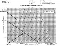
I drew the loadline for B+ = +325V, plate load resistor (Rp) = 150k ohms.
Notice that I labeled the plate voltage as Vp-k. That's voltage from plate to cathode. That will become important when you draw a loadline for the cathodyne, as the cathode will be somewhere around 100V above ground.
--
Notice that I labeled the plate voltage as Vp-k. That's voltage from plate to cathode. That will become important when you draw a loadline for the cathodyne, as the cathode will be somewhere around 100V above ground.
--
Attachments
Last edited:
Member
Joined 2009
Paid Member
I think you'll find that the difficulty is caused by having such a low B+. 320V is pretty low for a 6SL7. It would be a low B+ for a 6SN7 too. I think you're going to find that you need to operate the tubes with lower than optimal Ip (plate current), because of the lower than optimal B+.
I don't know if you have the space, but a choke instead of a resistor for the 6SL7 anode would allow more headroom. Hammond makes a 150H choke that might just be enough and is relatively inexpensive. The 6SN7 would be the first thing to try though, although it likes a high B+ for best linearity, it has a much lower plate resistance than the 6SL7.
If you could bear the thought of re-wiring, you could also try a combination, 6SL7 up front for gain, 6SN7 for phase splitter for more drive.
OK, let's say we have that same +325V B+ available for the 6SL7 cathodyne. We'll now want to draw a loadline for that, Let's say we have a plate load resistor (Rp) of 100k, and a cathode load resistor of 100k (Rk).
Since the current will be the same at all points in the circuit (Kirchoff's Law), then we can divide the B+ by 3, so 325/3 = 108 (approx, close enough)
100,000 x .00108 = 108V dropped across each 100k ohm resistor. (Wasn't that convenient?)
The voltage at the 6SL7 cathode will be +108V.
The voltage at the 6SL7 plate will be +216V.
The B+ will be +324V (close enough to 325 for our purposes).
As you can see, the voltage from the 6SL7 plate to cathode will be only 108V. The "B+" the 6SL7 will "see" will be from the cathode to the B+, which is 216V.
So, to draw the loadline, we use values of 216V and 100k ohms.
216V divided by 100,000 = 2.16mA ( NOT 21.6!!! )
I added (in brown) loadline for 182k ohms for plate and cathode load resistors.
These loadlines are attached.
--
Did I do that right??
--
I don't think the cathodyne will have to supply much current drive for 6V6 pentode outputs, so maybe a 6SL7 will do here. But it shouldn't be run with near zero bias, where the 6SL7 will be likely to start drawing current through its grid. That would load down the previous stage, which would not be good. My understanding is that high mu tubes like 6SL7 draw appreciable grid current when biased with anything less than about -1V at the grid. That's how they can be used with grid leak bias (a huge grid resistor and no cathode resistor). We don't want that happening in the cathodyne phase splitter, do we...
--
Since the current will be the same at all points in the circuit (Kirchoff's Law), then we can divide the B+ by 3, so 325/3 = 108 (approx, close enough)
100,000 x .00108 = 108V dropped across each 100k ohm resistor. (Wasn't that convenient?)
The voltage at the 6SL7 cathode will be +108V.
The voltage at the 6SL7 plate will be +216V.
The B+ will be +324V (close enough to 325 for our purposes).
As you can see, the voltage from the 6SL7 plate to cathode will be only 108V. The "B+" the 6SL7 will "see" will be from the cathode to the B+, which is 216V.
So, to draw the loadline, we use values of 216V and 100k ohms.
216V divided by 100,000 = 2.16mA ( NOT 21.6!!!
)I added (in brown) loadline for 182k ohms for plate and cathode load resistors.
These loadlines are attached.
--
Did I do that right??
--
I don't think the cathodyne will have to supply much current drive for 6V6 pentode outputs, so maybe a 6SL7 will do here. But it shouldn't be run with near zero bias, where the 6SL7 will be likely to start drawing current through its grid. That would load down the previous stage, which would not be good. My understanding is that high mu tubes like 6SL7 draw appreciable grid current when biased with anything less than about -1V at the grid. That's how they can be used with grid leak bias (a huge grid resistor and no cathode resistor). We don't want that happening in the cathodyne phase splitter, do we...
--
Attachments
Last edited:
I don't know if you have the space, but a choke instead of a resistor for the 6SL7 anode would allow more headroom. Hammond makes a 150H choke that might just be enough and is relatively inexpensive. The 6SN7 would be the first thing to try though, although it likes a high B+ for best linearity, it has a much lower plate resistance than the 6SL7.
If you could bear the thought of re-wiring, you could also try a combination, 6SL7 up front for gain, 6SN7 for phase splitter for more drive.
Good points all!
If you wanted to get really slick, why not a DN2540 FET as the plate load for the first stage?
But I don't think the first stage is the problem. I think the problem is the cathodyne phase splitter. Let's see if a 6SN7 would work better there...
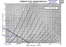
Well, I tried 15k for the plate and cathode load R's, but I came up with very little swing available. Maybe enough to drive 6V6's, though. With 15k load resistors, the 6SN7 operating current winds up at 7.2mA, which isn't bad. The only thing is I again worry about the tube needing to swing to near zero volts at its input, causing grid current, causing the input tube to go *crunch*.
With 22k (shown), the 6SN7 internal current is about 5mA (probably will be more like 4.9mA), which isn't as good, but isn't horrible. It swings more volts this way.
--
Swapping in a 6SN7 instead of the 6SL7 opens a new can of worms. The problem is that the gain of a 6SN7 common cathode stage with resistor plate load will be about 15x. So, with only +325V B+, the grid bias on that first stage 6SN7 is bound to be kind of low. So let's say it's -2V and the highest peak input (AC signal) voltage will be 1.7V. 1.7 x 15 = 25.5 volts out, but the cathodyne has actually less than 1x gain. Let's say 0.9. So, 25.5 x 0.9 = 22.95 volts out to drive the 6V6's. That's just barely enough, no headroom to speak of. That's the problem with swapping in the 6SN7 in place of the 6SL7.
In the end, I think Bigun's suggestion of a 6SL7 for the input voltage amplifier stage and 6SN7 for the cathodyne is the better way to go. The trick is to get the grid bias of the 6SL7 to about –1.5V, both so that you can give it enough input signal and so that it doesn't draw too much grid current (if too close to zero bias).
--
Attachments
Last edited:
In the first post, you posted the voltages you got as:
HV1 - 327 - B+
HV2 - 326 - Phase Inverter Stage
HV3 - 286 - Input Stage
V1PA - 65 - Input Plate Voltage
V1PB - 253 - Phase Inverter Plate Voltage
If cathodyne HV2 is +326V, and its plate voltage is +253V...
326 - 253 = 73
That's 0.73mA across the 100k plate resistor, so in accordance with Kirchoff, 0.73 being drawn by the tube too.
100k resistors in the plate and cathode, correct? That would mean 73V dropped across both the plate resistor and cathode resistor. So 73 x 2 = 146.
326 - 146 = 180.
That means there is 180V from the 6SL7's plate to its cathode ("across the tube").
This does not add up. But if it does add up, and the tube is actually different than the published curves, it still means the 6SL7 is being run down near cutoff (where it stops conducting), and won't swing many volts before going *crunch*.
So you see, we need to verify those voltage readings you got. They don't look good...
--
Awesome information, need to digest, but looks straight forward.
I will have to get the voltages re-checked. I might have to get a couple of different 6SL7's to try. I had a box of 5 JAN6SL7GT that I got off of EPay and I did swap one out for another and it had the same results. I will re-verify the voltages to make sure.
One thing that I can do to move the power supply voltage up a bit is remove the beloved 5U4GB and pop in a GZ34. I think that will push up the B+ another 20v or so, right to the edge of the 6v6. For grins, I'll get voltages for both.
Just need to have 1 day where I am not working 18 hours
Sandy
Last edited:
what 6v6 are those? are they sylvanias? guessing because of green lettering? lol im hunting for some damn better qauality 6v6 for my stealth current production sux well at least the jj imo I have 1955 CBS clear glass black-plates but they sound just ok really thinking i need some brimars or rcas or sylvanias not sure GE heard good and bad things about them. something is just missing/lacking with CBS
The 6V6's are Tungsol re-issues. I also have a set of JJ's that are supposed to be very good and can take a lot more plate voltage. Don't yet know how they sound or how they would sound in a Gutiar amp. I did not see a lot of 6v6's that were affordable on EPay, but you might find them if you poke around
Sandy
Sandy
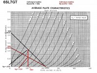
So many suggestions and tangents in this thread, I'm betting the op is more confused than helped. So just a simple graphical explanation of what your early clipping issue is. Based on your original posted schematic, the first pic is what your operating point and load line look like on the 6sl7 plate curves. I must say it is horrible, very little room for voltage swing in the negative direction. Simplest way to get it more in line, although not the best, is to change r16 47k to 1k, r8 270k to 220k, and r7 1k to 1.3k - 1.5k to get approx. 110 volts on the plate.
Attachments
Last edited:
Sandy you are right about the about JJ handling High B+ on plates in my stealth I had 420v on plates and they laughed at that had em biased around 22ma so cranked bias pot all the way had em to like 30-32ma and they still laughed not hint of red-plating they are a super monster tube They sound great for clean stuff but distorted tones I don't care for huge bass response but highs were all ice pick and sterile. I was thinking about trying the Tungsol or the EH, heard the Tungsol is smooth and sounds close to RCA glass and EH is more crunchy also heard EH is bad about the screen grid failures and the stealth has screens around 400V so I might be taking a chance.
So many suggestions and tangents in this thread, I'm betting the op is more confused than helped. So just a simple graphical explanation of what your early clipping issue is. Based on your original posted schematic, the first pic is what your operating point and load line look like on the 6sl7 plate curves. I must say it is horrible, very little room for voltage swing in the negative direction. Simplest way to get it more in line, although not the best, is to change r16 47k to 1k, r8 270k to 220k, and r7 1k to 1.3k - 1.5k to get approx. 110 volts on the plate.
I totally agree. Thank you for putting that so simply.
How did I miss that R16 is 47k?
 Why such a large value? The input stage would benefit greatly from a higher B+. Reducing that 47k to 1k means its associated decoupling cap will need to 100uF, but that's not a difficult value to find.
 --
Also, the phase splitter is biased way down near zero volts, and that could be a problem too.
For the input stage. What is the p-p signal you are sending into the input of the amp? Your supply is 286VDC. You are dropping 40V from HV2 to HVinput across a 47k resistor so you are drawing approximately 0.85mA current. Looking at the 6SL7 loadline, you are biased at about 0.7V - ish. What is the reading on the first input cathode (pin3)? Is it close to 0.7v? If you are sending in a signal greater than 1.5V p-p you are probably clipping here. If your CD player or whatnot send smaller signals, this is fine. Looks to be set up to get max gain up to input signals of 1Vpp
On the phase inverter, you have a similar problem with "headroom" as the others already stated. I would reduce r9/r14 and see what happens first. I think this is your bigger problem unless you are just nailing the input with a huge signal, which would cause an input AND PI problem.
On the phase inverter, you have a similar problem with "headroom" as the others already stated. I would reduce r9/r14 and see what happens first. I think this is your bigger problem unless you are just nailing the input with a huge signal, which would cause an input AND PI problem.
- Status
- This old topic is closed. If you want to reopen this topic, contact a moderator using the "Report Post" button.
- Home
- Amplifiers
- Tubes / Valves
- New 6V6 Build - Suggestions Needed