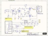
Back again for some help on a 6V6 Project. I Mashed together a few different schematics and came up with the EZ10. Trying to make a pair of small mono-blocks for my office and figured I would try an all octal 6V6 based amp.
The circuit is a cross between the Silvertone and the Dynaco 6V6 using ultra-linear.
Initial testing looks awesome, except for early clipping early at about 5watts. Power transformer and output transformer are about 2x the required size so pretty confident it's in the input stage.
Waveforms (sine and square) before it gets into clipping are beautiful across the audio range, so off to a pretty good start!
I need some help in getting the right operating points for the each of the sections for the 6SL7 and getting the power supply in order to set that up.
Other then trial and error what are good places to start (current and voltage) for this type of amplifier? And how to apply the math") so I can learn a bit.
so I can learn a bit.
My Initial voltage measurement seems like the plate voltage on the input stage is way too low (maybe not the inverter stage).
From the test points on the board, with no signal, connected to load 8ohm, and rectifier tube as a 5U4GB, and 270ohm cathode resistor -
Bias Voltage across Cathode resistor (270ohm) 21v, and current measured at each 6V6 Tube at about 37ma (might be a tad high)
So the big question is what are good operating points for the 6SL7 and how do I figure it all out the math for the resistor (is it just simple voltage drop once I find the operating point???)
As always thanks for any help folks have to offer!
Sandy
The circuit is a cross between the Silvertone and the Dynaco 6V6 using ultra-linear.
Initial testing looks awesome, except for early clipping early at about 5watts. Power transformer and output transformer are about 2x the required size so pretty confident it's in the input stage.
Waveforms (sine and square) before it gets into clipping are beautiful across the audio range, so off to a pretty good start!
I need some help in getting the right operating points for the each of the sections for the 6SL7 and getting the power supply in order to set that up.
Other then trial and error what are good places to start (current and voltage) for this type of amplifier? And how to apply the math
so I can learn a bit. My Initial voltage measurement seems like the plate voltage on the input stage is way too low (maybe not the inverter stage).
From the test points on the board, with no signal, connected to load 8ohm, and rectifier tube as a 5U4GB, and 270ohm cathode resistor -
Code:
HV1 - 327  - B+
HV2 - 326  - Phase Inverter Stage
HV3 - 286  - Input Stage
V1PA - 65  - Input Plate Voltage
V1PB - 253 - Phase Inverter Plate VoltageSo the big question is what are good operating points for the 6SL7 and how do I figure it all out the math for the resistor (is it just simple voltage drop once I find the operating point???)
As always thanks for any help folks have to offer!
Sandy
Attachments
Hey Sandy,
I just built a 6V6 version of Dynaco's "Low Power High Quality Amplifier." and I ran into the same problems. I'm an amateur so my advice should be taken with a grain of salt.
The first thing I noticed is your schematic specs a GZ34 rectifier and you're using a 5U4GB. I think this might be a mistake. The GZ34 has a voltage drop of ten volts. The 5U4GB has a drop of 50 volts. This may explain why your voltages are low across the board.
The second thing is the feedback circuit. Most of these older designs drew feedback from a 16ohm tap. An 8ohm output has considerably less voltage than a 16ohm. So I would replace that 10k feedback resistor with a 10k pot and then tune the circuit while listening to it. The first time I did this I was amazed at how much the sound varies with feedback amount. Too little feedback and the amp will be distorted and tinny. Too much and it will sound flat and dull.
My two cents, Kevin
If you are willing to try a 6SN7......
I'm more of a fan of 6SN7 tubes running with a little more current. ( 2.5ma min)
R8 to 47k 1watt or 33k 1 watt to run at about 3.5ma
R7 1200 to 1500ohms to bias cathode to about 90v to drive the cathodyne. 93 volts across the cathode resister, 93 volts across the tube, 93 volts across the anode resister.
C6, leave out
R9, R14 to 33k 1watt that will run the cathodyne at 2.7ma.,to 27k 1watt that will run the cathodyne at about 3.5ma
Google for valve/tube data sheets. Then Google for valve/tube load lines.
I have the data sheet and will look at some of the google results. Hopefully it will start to make sense!
Sandy
Hey Sandy,
I just built a 6V6 version of Dynaco's "Low Power High Quality Amplifier." and I ran into the same problems. I'm an amateur so my advice should be taken with a grain of salt.
The first thing I noticed is your schematic specs a GZ34 rectifier and you're using a 5U4GB. I think this might be a mistake. The GZ34 has a voltage drop of ten volts. The 5U4GB has a drop of 50 volts. This may explain why your voltages are low across the board.
The second thing is the feedback circuit. Most of these older designs drew feedback from a 16ohm tap. An 8ohm output has considerably less voltage than a 16ohm. So I would replace that 10k feedback resistor with a 10k pot and then tune the circuit while listening to it. The first time I did this I was amazed at how much the sound varies with feedback amount. Too little feedback and the amp will be distorted and tinny. Too much and it will sound flat and dull.
My two cents, Kevin
Kevin - Thanks for the tips, the GZ34 / 5U4 swap was to keep the B+ voltage under 350, with the GZ34 it was a bit higher then the tubes recommended voltage. I have some JJ 6V6's that would be fine with it, but for starters I figured I would keep it closer to stock 6V6 specs while I figure things out with a good baseline of testing. The 10k pot is likely a good idea for testing as well.
Sandy
C6 shorts out the feedback. Put 100Ohms between C6/R5 and GND and connect the feedback there. Be sure to have negative feedback otherwise happy tinnitus.
Yep, forgot to put a optional resistor in that part of the circuit. Currently C6 is OPEN and not used, but put it in since I had some extra room on the board and might want to experiment with it. For now will be left open, but will update the schematic to add it in.
Sandy
If you are willing to try a 6SN7......
I'm more of a fan of 6SN7 tubes running with a little more current. ( 2.5ma min)
R8 to 47k 1watt or 33k 1 watt to run at about 3.5ma
R7 1200 to 1500ohms to bias cathode to about 90v to drive the cathodyne. 93 volts across the cathode resister, 93 volts across the tube, 93 volts across the anode resister.
C6, leave out
R9, R14 to 33k 1watt that will run the cathodyne at 2.7ma.,to 27k 1watt that will run the cathodyne at about 3.5ma
I like the 6SN7's too, have a bunch. The question on this will the 6SN7 have enough gain vs. the 6SL7? I will have to look at the data sheet and see if I can figure it out but my guess is that it will be lower then the 6SL7?
Learning as I go
Sandy
6SL7 is much higher gain especially with a 270K in the anode. Personnel preference to lower gain stages, lower output impedances, good stable drive stages to the next stage and minimal GNFB needed to keep it clean at full swing. You have both to play with, so have fun! From you earlier post you have extra current to play with if you use the GZ34 with less of a drop.... so you can run the first couple stages hotter to bring the B+ down a little.
Last edited:
Back again for some help on a 6V6 Project. I Mashed together a few different schematics and came up with the EZ10. Trying to make a pair of small mono-blocks for my office and figured I would try an all octal 6V6 based amp.
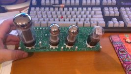
I looked at the photos and see a PCB. Did you actually built a printed circuit BEFORE you had a working prototype bread board. That requires more faith in your design than I ever have.
Do you have a scope? If so it should be easy to see where the amp is clipping. If I have to guess I'd guess you are not driveling the 6V6 with a large enough signal. Take out the NFB and add back the cathode cap that is now "open" and see if it still clips.
Yep, made the boards up prior to trying the circuit. It was a pretty simple circuit so much could be done before saying the boards are worthless . I have 2 issues with the board, forgot to connect the 2 stages together on the SN7' (Pin 2 to 4) easy fix, and a lead spacing on a few caps are too narrow... oops one more forgot the resistor in the feedback loop if the capacitor is used on the bottom leg of the input (not sure I'll use the cap).
Half the fun was fitting all the parts to the board and then trying to get that to fit in a small 6"x10" hammond chassis with all the iron.
The EZ260 amp was a lot more complicated (Grommes 260A Clone), this one was not too bad due to low parts count and really simple design.
Just need to get a bit of time and fiddle with the parts to dial it in.
Yep, have a couple of scopes, I'm 99% sure it's in the first stage just due to the low plate voltage but will hit it with the probe and confirm.
Sandy
. I have 2 issues with the board, forgot to connect the 2 stages together on the SN7' (Pin 2 to 4) easy fix, and a lead spacing on a few caps are too narrow... oops one more forgot the resistor in the feedback loop if the capacitor is used on the bottom leg of the input (not sure I'll use the cap).Half the fun was fitting all the parts to the board and then trying to get that to fit in a small 6"x10" hammond chassis with all the iron.
The EZ260 amp was a lot more complicated (Grommes 260A Clone), this one was not too bad due to low parts count and really simple design.
Just need to get a bit of time and fiddle with the parts to dial it in.
Yep, have a couple of scopes, I'm 99% sure it's in the first stage just due to the low plate voltage but will hit it with the probe and confirm.
Sandy
Try 150k for the anode resistor of the first stage (6SL7), with the 1k cathode resistor. That should get you in the neighborhood of 90V. As a rule of thumb for a split load splitter/inverter you want the anode to be approximately 2/3 of the anode supply and the cathode at 1/3. I know everybody here is pushing their darling 6SN7 (mine too), but you may just need that little extra gain up front for some GNFB.
Last edited:
Try 150k for the anode resistor of the first stage (6SL7), with the 1k cathode resistor. That should get you in the neighborhood of 90V. As a rule of thumb for a split load splitter/inverter you want the anode to be approximately 2/3 of the anode supply and the cathode at 1/3. I know everybody here is pushing their darling 6SN7 (mine too), but you may just need that little extra gain up front for some GNFB.
Ok, trying to learn to fish here
Can you help with some of math so I can see how to calculate this?One thing that I do have a question is that I see quite of few 6SL7's with the cathode resister in the 1.5k-3k range vs. the 1k that I 'picked' for this amp. Is the 1k value too low or is it not super critical??
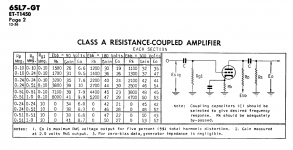
In the 6SL7 GE Datasheet it shows the sample for the 'Resistive Coupled Amp' with a table of resistors which in most cases are > 1k.
One thing that did confuse me was that plate voltage target and Ebb are not the same, so in my case the measured Ebb was about 286v with the 270k plate resistor.
Learning as I'm going but hopefully questions are meaningful!
Sandy
Attachments
Last edited:
Ok found out a couple of things, 1st, amp making fair power, I calculated the power output wrong. OOPS Mistake.
Amp putting out 8.5VRMS into 7.8ohms resistive load, so about 9 watts of output before clipping.
Calculated the voltage drop across the input stages Cathode Resistor (R7 1K) initially at .7ma (.71v drop) with the 270k plate resistor.
After changing the plate resistor to 150k the voltage drop was right at 1ma for the input stage. Up from .7ma.
The phase inverter resistor are 103k (ran out of 100k's) and see a 105V drop across both R14 and R9. So about 1ma on each of the resistors. DOES this mean 2ma tube current????
Sandy
The cathodyne is an in series device, so 1ma through it. It appears to be close to center biased, so how does it sound? and what can you get out it it before clipping?
It's putting out a bit over 9 watts as I calculated it. I have only tried it on a small speaker so can't say at all how it sounds as yet. Will need to put it in the chassis before I can move the mess of wires near some reasonable speakers.
Is the 1 ma too low for the phase inverter stage? Seems like the amp should do a bit more then 9 watts before it gets into clipping. Or is this common for 6v6 amps?
Power supply is much larger then needed as well as the choke (7H) and 15w output transformer (All Edcor).
I'm running an 8K impedance ultra linear edcor output trans, might I have been better off running something lower like a 5k?
I have also not messed with the negative feedback either, but signals look very clean just can't comment on sound quality as yet.
Sandy
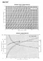
I have the plate curves for 6SL7GT. I attached them below.
You gave us voltages with "no load." Does that mean there were no tubes in the sockets? Or does that mean there was no signal going into the amp? Could you put the tubes in, power up the amp with no signal applied, and give us the voltages at all the tubes' plates and cathodes, and the voltages of the HV feeds?
With HV2 at +326V, and +200V on the plate of the cathodyne 6SL7, that means there's 126V dropped across the 100k plate resistor, which means 1.26mA through the cathodyne. The 100k resistor in the cathode would also drop that same 126V. So...
126 + 126 = 252V dropped across the two 100k resistors. That leaves a plate-to-cathode voltage of only 70V across the 6SL7 (252 + 70 = 326). With only 70V plate voltage and 1.25mA across the tube, that would put the tube down near zero bias, cathode to grid. Crunch!
I think we need measured voltages with the circuit operating before anybody will be able to give you useful advice.
That circuit should work fine, even with 6SL7 as the voltage amp and cathodyne phase splitter. It looks to me like the cathodyne should have no more than about 0.7mA through it. I think you want to get the bias on the 6SL7 up to about 1.5V (cathode positive to grid).
--
Also wanted to add -- After looking at the 6SL7 curves, it looks to me that this is a tube that needs a high B+ to work with. The loadline for B+ = 300V and a 100k plate resistor looks very steep, which would give you higher distortion, with a higher proportion of 3rd harmonic likely. Redraw the loadline with 400V and a 270k plate resistor and things look much better.
--
Attachments
Last edited:
Your problem may be due to the heater supply for the 6sl7-gt, as it is a twin triode. With some values if this type when they are use one half for one channel and other for the otherchannel.One of the channels is found to have less gain. This happens because the heater goes in to one cathode and then in to the next. Some thing you can try is if you have a spare 6sl7-gt using one triode section from one of the tubes for v gain and the other for the inversion..
- Status
- This old topic is closed. If you want to reopen this topic, contact a moderator using the "Report Post" button.
- Home
- Amplifiers
- Tubes / Valves
- New 6V6 Build - Suggestions Needed