I have many questions spinning in my head about advantages and problems related to "size" of output transformers, without a rule of thumb. Having wound a few, there seem to be considerable complications in making a really really good large push/pull output transformer. Later outer windings have more resistance per winding turn. High resistance of long wires for large windings requires heavier-guage wire.
I've used transformer outputs in series for voltage, but never in parallel... For one channel, can I just use 4 identical smaller lower-wattage output transformers, with inputs and outputs in series then those series-pairs in parallel? Hopefully each tranny would handle half the voltage and half the current. Are there resonance problems with audio-frequency transformer inputs or outputs in parallel? If it works, I can see some advantages, like PERFECTLY matched push and pull sides without complicated winding patterns, compact low-resistance coils around half-size cores. I imagine there might be a little more total iron weight with 4? But all coils would be smaller, around half-size cores, push and pull sides could match PERFECTLY. Small-signal performance might improve (or not). I just don't know the dangers and downsides of parallel... If there's some imbalance and cross-coil flow in paralleled inputs, don't they disappear in the paralleled outputs? Or is there a better multi-tranny scheme, with primarys in series and outputs in parallel, to reduce the turns ratio?
Not discussing cost here, just performance...just need to get a weird idea clarified and out of my head.
Thanks.
As one case. But many others. For instanace, very large mono bass amps use enormous output transformers. Several smaller output transformers might work much better (and be easier to package, and have more surface area for cooling, and smaller windings), IF their outputs (secondary windings) can be paralleled.
I hesitated to write about such an approach being afraid that prices on flathead signal transformers may skyrocket. I used them with primaries in series, secondaries in parallel. They have quite good insulation between windings, so it is safe to stack them for P-P guitar amps.
idea of multiplying small vintage output transformers is on my mind for some years.. and i recall i've read something like someone on Triode festival having an OT, which was in fact multiple small vintage transformers inside the can. but i can't find any info about this practice (no wonder)
my personal aim is to try effect of old iron/wire/winding to mids and highs, while gaining some H for lows. Is there one rational way to do it ? Can i treat primaries and secondaries just as a separate coils, ignoring the fact they are on different cores?
thanks for opinions
my personal aim is to try effect of old iron/wire/winding to mids and highs, while gaining some H for lows. Is there one rational way to do it ? Can i treat primaries and secondaries just as a separate coils, ignoring the fact they are on different cores?
thanks for opinions
I'm considering schemes where the output secondaries from multiple transformers end up in parallel. But is that ill-advised?
With a stereo tube amp that has a ground referenced output, you can parallel the two channels (with the same input signal to both channels).
For a 4 Ohm speaker (on one of the 4 Ohm taps), jumper the 8 Ohm taps.
For an 8 Ohm speaker (on one of the 8 Ohm taps), jumper the 16 Ohm taps.
With two identical mono tube amps (with the same input signal to both), jumper the taps as above, and also the 0 Ohm (ground) taps.
Last edited:
I've used transformer outputs in series for voltage, but never in parallel... For one channel, can I just use 4 identical smaller lower-wattage output transformers, with inputs and outputs in series then those series-pairs in parallel?
Remember that the net DC current in a transformer primary must be zero to avoid saturation in a core without a gap.
This condition is satisfied in a standard push-pull circuit, since the two plate currents flow in opposite directions in their winding halves.
This would not happen in the connection that you suggest.
If I understand correctly, OP want to parallel two series pair of OPT. That is first taking two OPT and series both the primary and secondary. Wire up another pair exactly like the first pair. Then parallel both series pairs. Just like taking 4 8 ohm speaker, put two in series, then parallel the two pair and get the final impedance of 8ohm.
First pass, the impedance part seems to work out, you created a composite OPT.
BUT that does not work at all. The reason is when you connect two primary in series, the point where the two primary connect together becomes the center tap. The DC current through the primary for push pull will not be cancelled because the two opposite currents are on different core. So you don't have cancellation of the magnetic flux. You need to have gaped core to handle the net DC current. That complicates the design again.
... very large mono bass amps use enormous output transformers. Several smaller output transformers might work much better (and be easier to package, and have more surface area for cooling, and smaller windings), IF their outputs (secondary windings) can be paralleled.
A large core with a high number of windings on the primary gives a high magnetising inductance. If the magnetising inductance is not high enough, bass frequencies will be shunted to (AC) ground.
I have done a quite a bit with SMPS transformers.
I got caught out once using parallel windings on the secondary.
I didn't have exactly the same number of turns on each and it caused massive current to flow.
So you need to make sure both transformers are exactly matched.
Or you could use twin primaries in parallel and have the outputs go to separate speakers.
I have done several multi OPT experiments.
Parallelling OPT primaries reduces the inductance. This might be OK if the driving tubes are also paralleled.
If you are making a P-P amp with seriesed primary OPT's everything must be symmetrical and the net DC in each OPT must cancel. If you use OPT's with split primaries like a 120/240 volt mains transformer, you can insert one transformer "inside" another to satisfy both conditions. This imposes 2X the B+ or more on the outer transformers insulation.
In most high powered tube amps multiple pairs of output tubes are used. The simplest solution and the one that has worked for me is to use one P-P OPT for each pair of output tubes. Each pair of tubes has its own DC adjustments but all tube pairs receive identical drive.
For a 4 tube amp wire the OPT secondaries in parallel and load the amp with half the usual impedance. Use a 4 ohm load on an 8 ohm OPT. For multi tapped secondaries, connect all identical taps in parallel, and connect the 8 ohm load to the 16 ohm tap.
For large amps of say 8 tubes wire two pairs up to two OPT's as described above. Make another identical setup, except reverse the phase in the OPT primaries (swap the blue and brown wires) ground the 0 ohm taps on both OPT's and use them in series. An 8 ohm load would be connected across the 8 ohm taps. This is a series parallel arrangement.
I had breadboarded a 400 watt amp using 8 X 13GB5 tubes and 4 X identical 80 watt guitar amp OPT's. It would make almost 500 watts at clip on 650 volts with just a hint of red glow in the tubes. All 8 tubes were driven by Pete Milletts P-P driver board with 6HB6 tubes installed.
I have done several multi OPT experiments.
Parallelling OPT primaries reduces the inductance. This might be OK if the driving tubes are also paralleled.
If you are making a P-P amp with seriesed primary OPT's everything must be symmetrical and the net DC in each OPT must cancel. If you use OPT's with split primaries like a 120/240 volt mains transformer, you can insert one transformer "inside" another to satisfy both conditions. This imposes 2X the B+ or more on the outer transformers insulation.
In most high powered tube amps multiple pairs of output tubes are used. The simplest solution and the one that has worked for me is to use one P-P OPT for each pair of output tubes. Each pair of tubes has its own DC adjustments but all tube pairs receive identical drive.
For a 4 tube amp wire the OPT secondaries in parallel and load the amp with half the usual impedance. Use a 4 ohm load on an 8 ohm OPT. For multi tapped secondaries, connect all identical taps in parallel, and connect the 8 ohm load to the 16 ohm tap.
For large amps of say 8 tubes wire two pairs up to two OPT's as described above. Make another identical setup, except reverse the phase in the OPT primaries (swap the blue and brown wires) ground the 0 ohm taps on both OPT's and use them in series. An 8 ohm load would be connected across the 8 ohm taps. This is a series parallel arrangement.
I had breadboarded a 400 watt amp using 8 X 13GB5 tubes and 4 X identical 80 watt guitar amp OPT's. It would make almost 500 watts at clip on 650 volts with just a hint of red glow in the tubes. All 8 tubes were driven by Pete Milletts P-P driver board with 6HB6 tubes installed.
Do you mean the two options are
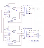
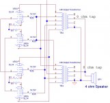
1) parallel output of the OT secondary, use the paralleled 8 ohm taps to drive 4 ohm speaker. Each of the primary of the OT is driven by a separate pair of power tubes as show in the first drawing.
2) parallel every single connection of the two OT, also parallel the two pair of tubes as shown. 4 ohm speaker connect to the parallel of the two 8 ohm tap of the two OT. as in the second drawing.
Looks like it should work. Is there any advantage of using two lower wattage smaller size OT like this?
Attachments
I had breadboarded a 400 watt amp using 8 X 13GB5 tubes and 4 X identical 80 watt guitar amp OPT's. It would make almost 500 watts at clip on 650 volts with just a hint of red glow in the tubes. All 8 tubes were driven by Pete Milletts P-P driver board with 6HB6 tubes installed.
650 volts, are you serious? are those tubes still alive?

Norman Crowhurst did a twin-coupled amp on the same theme of having multiple opts'...http://www.audiofaidate.org/it/articoli/TwinCoupledcrowhurst.pdf
The inductance of a coil, on a single core, depends on the square of the number of turns. Let's say we replace a single transformer with say 200 turns on the primary with two transformers, with 100 turns each on their primaries, in series. (This way we would have the right voltage and current.) The overall magnetising inductance will be halved. Plus the two (smaller) cores will each have higher magnetic reluctance than the single large core, again reducing the overall magnetising inductance.
Is there any advantage of using two lower wattage smaller size OT like this?
In my case I did this because I have a good supply of identical cheap P-P OPT's that are good for 25 to 100 watts depending on application.
I would assume that a single correctly chosen and built OPT for a given application would be the optimum choice. However, off the shelf OPT's for a 400 watt per channel amp aren't too common. I do have a pair of Plitron 400 Watt toroidal OPT's that will be used for my eventual monster amp, but I am not in a big hurry to build that one yet.
OPT's get more complicated as the size goes up. To get good bass you need enough iron and wire to get enough inductance and magnetic capability. To get good high frequency response you need to minimize leakage inductance and interwinding capacitance. Both of these go up with size, so extra interleaving, and special winding techniques are needed. At some point a big OPT with HiFi frequency response will become cost prohibitive.
In the case of a Musical Instrument amplifier, multiple speakers are common. It makes sense to build multiple 50 to 100 watt amps, all driven by the same source, and connect each to a separate cabinet, or series-parallel connect them as needed.
In each of your diagrams you have the grids tied in parallel. I used a separate coupling cap and bias adjustment for each tube. You need to keep the bias currents equalized.
650 volts, are you serious? are those tubes still alive?
Yes, they are.
I got 150 13GB5's from ESRC in trade for a bunch of NOS good stuff that I had in small and odd numbered quantities. About 135 of them were all Mullard made regardless of which brand was on the tube, and 15 were Korean (Samsung?).
I got a pair of each and "tested" them. A class AB amplifier will dissipate the most heat at about half power. I set up a simple test amp using Pete's driver board and a pair of 13GB5's on perf board. The driver board was fed 450 volts, and the output tubes were connected to my big HP power supply that goes up to 650 volts at 1.7 amps. I tried OPT's from 2500 ohms to 6600 ohms and found that 3300 ohms gave the most efficiency with the Mullard tubes. I could get 120 watts from a pair of Mullard tubes at 650 volts without blowing anything up. The Korean tubes red plated badly in the same setup at any combination of voltage and OPT that resulted in more than 80 watts output. I banged on a pair of Mullard tubes until the bright yellow "Sylvania" lettering turned brown but the tubes just kept going.
I ran through a bunch of tubes and picked two sets of 8 with similar Gm. In the back of my mind I was thinking of 16 tubes, a certain pair of 1250 ohm Plitrons, and a 400 WPC amp would be easy....I have since changed my mind, but it will likely change again before I build it.
Then I built the single channel monster test amp on a piece of perf board just for fun. The fun ended when I accidentally blew up the driver board by plugging the power supply cable in upside down, running 450 volts through the board backwards.
This test amp ran for nearly an hour at almost 500 watts on 650 volts with no issues. There was a pale redness in a couple of tubes in a dark room. The tubes did get quite red as I reduced the drive to about 250 watts output. I did test at lower voltages, and somewhere in my notes I have the results. I decided that for an amp that sees MI duty, I would run those tubes in the 75 watt range. 100 WPC is probably OK for a HiFi amp since it will only see that level on peaks. You can get there on about 575 volts and 3300 ohms. If you wanted to play sine waves forever at full power, keep them to 50 watts per pair.
All those experiments were done in conventional G1 drive. I started working with the 13GB5 in screen drive, and G1 + G2 drive using a single pair of tubes. I had an amp that would squeeze 150 watts from a single pair of these little tubes, and was about to test it with some big sweep tubes, when everything ceased.
I had to pack up everything and leave Florida on 3 weeks notice, so no more experiments have taken place. There will be no more until my new lab is built, which is ay least 6 months away....probably more.
In my case I did this because I have a good supply of identical cheap P-P OPT's that are good for 25 to 100 watts depending on application.
OPT's get more complicated as the size goes up. To get good bass you need enough iron and wire to get enough inductance and magnetic capability. To get good high frequency response you need to minimize leakage inductance and interwinding capacitance. Both of these go up with size, so extra interleaving, and special winding techniques are needed. At some point a big OPT with HiFi frequency response will become cost prohibitive.
In each of your diagrams you have the grids tied in parallel. I used a separate coupling cap and bias adjustment for each tube. You need to keep the bias currents equalized.
You said you use guitar OPT for your audiophile amp use, what OPT are you using? How is the frequency response and sound?
Is there any way to use different OPT in parallel, use the small one for mid and tweeter, then a big one for driving the woofer. Only problem is you cannot have have GNFB as the secondary of the two OPT is not in parallel anymore.
I have a few OPT from guitar amps, a Marshall 100W for 4 6550, another 50W for 2 6L6 and another one for Fender Bandmaster type by Classic Tone. I was planning to buy the Lundahl to start, but is there any virtue of experiment with cheap OPT.
In my case I did this because I have a good supply of identical cheap P-P OPT's that are good for 25 to 100 watts depending on application.
I would assume that a single correctly chosen and built OPT for a given application would be the optimum choice. However, off the shelf OPT's for a 400 watt per channel amp aren't too common. I do have a pair of Plitron 400 Watt toroidal OPT's that will be used for my eventual monster amp, but I am not in a big hurry to build that one yet.
OPT's get more complicated as the size goes up. To get good bass you need enough iron and wire to get enough inductance and magnetic capability. To get good high frequency response you need to minimize leakage inductance and interwinding capacitance. Both of these go up with size, so extra interleaving, and special winding techniques are needed. At some point a big OPT with HiFi frequency response will become cost prohibitive.
In the case of a Musical Instrument amplifier, multiple speakers are common. It makes sense to build multiple 50 to 100 watt amps, all driven by the same source, and connect each to a separate cabinet, or series-parallel connect them as needed.
In each of your diagrams you have the grids tied in parallel. I used a separate coupling cap and bias adjustment for each tube. You need to keep the bias currents equalized.
yes.....bigger OPT's are a bit harder to make...so multiple smaller ones are more practical imho....
but you know, the urge to go big is always there....
Yes, they are.
I got 150 13GB5's from ESRC in trade for a bunch of NOS good stuff that I had in small and odd numbered quantities. About 135 of them were all Mullard made regardless of which brand was on the tube, and 15 were Korean (Samsung?).
I got a pair of each and "tested" them. A class AB amplifier will dissipate the most heat at about half power. I set up a simple test amp using Pete's driver board and a pair of 13GB5's on perf board. The driver board was fed 450 volts, and the output tubes were connected to my big HP power supply that goes up to 650 volts at 1.7 amps. I tried OPT's from 2500 ohms to 6600 ohms and found that 3300 ohms gave the most efficiency with the Mullard tubes. I could get 120 watts from a pair of Mullard tubes at 650 volts without blowing anything up. The Korean tubes red plated badly in the same setup at any combination of voltage and OPT that resulted in more than 80 watts output. I banged on a pair of Mullard tubes until the bright yellow "Sylvania" lettering turned brown but the tubes just kept going.
I ran through a bunch of tubes and picked two sets of 8 with similar Gm. In the back of my mind I was thinking of 16 tubes, a certain pair of 1250 ohm Plitrons, and a 400 WPC amp would be easy....I have since changed my mind, but it will likely change again before I build it.
Then I built the single channel monster test amp on a piece of perf board just for fun. The fun ended when I accidentally blew up the driver board by plugging the power supply cable in upside down, running 450 volts through the board backwards.
This test amp ran for nearly an hour at almost 500 watts on 650 volts with no issues. There was a pale redness in a couple of tubes in a dark room. The tubes did get quite red as I reduced the drive to about 250 watts output. I did test at lower voltages, and somewhere in my notes I have the results. I decided that for an amp that sees MI duty, I would run those tubes in the 75 watt range. 100 WPC is probably OK for a HiFi amp since it will only see that level on peaks. You can get there on about 575 volts and 3300 ohms. If you wanted to play sine waves forever at full power, keep them to 50 watts per pair.
All those experiments were done in conventional G1 drive. I started working with the 13GB5 in screen drive, and G1 + G2 drive using a single pair of tubes. I had an amp that would squeeze 150 watts from a single pair of these little tubes, and was about to test it with some big sweep tubes, when everything ceased.
I had to pack up everything and leave Florida on 3 weeks notice, so no more experiments have taken place. There will be no more until my new lab is built, which is ay least 6 months away....probably more.
afaik, these tubes sell for about U$1 each still....i have 40 of these and intend to make an amp out of these soon.....i have seen a PL504 pp amp for 200 watts using six of these tubes....
- Status
- This old topic is closed. If you want to reopen this topic, contact a moderator using the "Report Post" button.
- Home
- Amplifiers
- Tubes / Valves
- multiple output transformers per channel