Now that I have your attention can I call upon the gurus to help me with a problem....
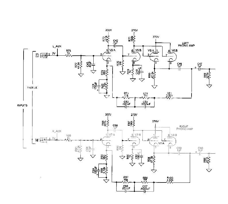
I just finished building a phono preamp head unit ( no power supply yet) and based the circuit around the Mcintosh MC2200 preamp (see attached), this circuit was almost exactly the same as on paper, the only differences are when I used more standard values of parts that I had available, I.E a 1K resistor in the first stage cathode instead of the 953 ohm....
All voltages are correct to within a couple of volts in the CF stage, the heaters are up at 100V from a decade of two 100K in series from the 200V rail. (CF at 135V) So plenty of headroom there....
The sound? well to my ears absolutely fantastic! who would have thought a feedback RIAA would work so well. But here's the problem.....
When running into my MC275 the plates on the KT88 run red hot. Even at low low volume. This surprised me because I am limiting the volume input with the amps pots and the output from the preamp is no louder than standard RCA jack levels. There is no DC on the output.
After a minute running hot I had a small flash over. This convinced me not to try again until the problem is resolved. Perhaps it is some sort of out of band frequency, sub or super sonic that is driving the amp crazy. I would have thought I would get some sort of indication but the sonics are sweet and non-distorted.
The HT is 270V from a 6l6 regulated bench top supply, (very clean) the heater supply for testing is a 12 Volt car battery.
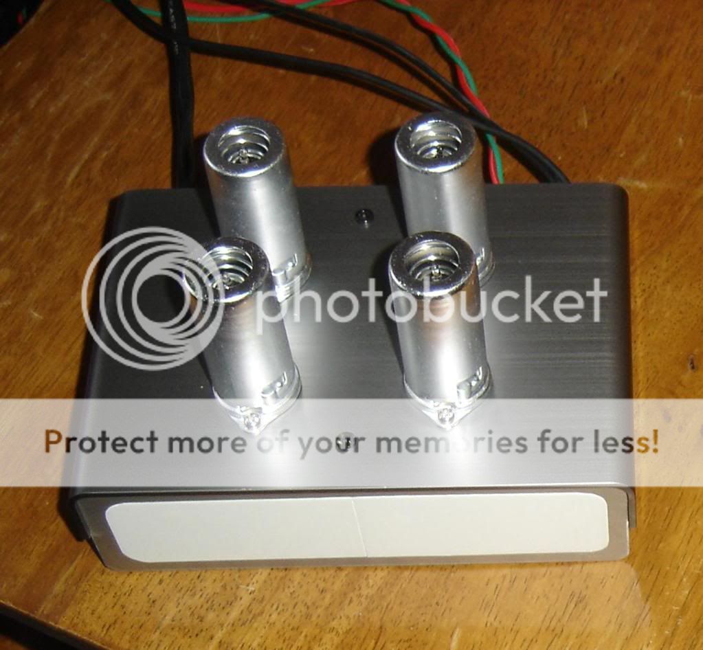
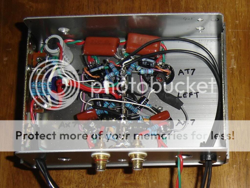
I would have build SYs phono preamp but who can afford the parts? this preamp was made with all leftovers, including a chassis bought in Japan 10 years ago.... hence some odd looking bits and pieces....
Help me Obi-Wan
I just finished building a phono preamp head unit ( no power supply yet) and based the circuit around the Mcintosh MC2200 preamp (see attached), this circuit was almost exactly the same as on paper, the only differences are when I used more standard values of parts that I had available, I.E a 1K resistor in the first stage cathode instead of the 953 ohm....
All voltages are correct to within a couple of volts in the CF stage, the heaters are up at 100V from a decade of two 100K in series from the 200V rail. (CF at 135V) So plenty of headroom there....
The sound? well to my ears absolutely fantastic! who would have thought a feedback RIAA would work so well. But here's the problem.....
When running into my MC275 the plates on the KT88 run red hot. Even at low low volume. This surprised me because I am limiting the volume input with the amps pots and the output from the preamp is no louder than standard RCA jack levels. There is no DC on the output.
After a minute running hot I had a small flash over. This convinced me not to try again until the problem is resolved. Perhaps it is some sort of out of band frequency, sub or super sonic that is driving the amp crazy. I would have thought I would get some sort of indication but the sonics are sweet and non-distorted.
The HT is 270V from a 6l6 regulated bench top supply, (very clean) the heater supply for testing is a 12 Volt car battery.
I would have build SYs phono preamp but who can afford the parts? this preamp was made with all leftovers, including a chassis bought in Japan 10 years ago.... hence some odd looking bits and pieces....
Help me Obi-Wan
An externally hosted image should be here but it was not working when we last tested it.
Hi TV7
I may be the "guru" you like to get advice from.
Using standard 5% values for the components is in my opinion quite OK. The effects from variation of gain from tube to tube is probably much greater than the effects of the resistor tolerances. The simplest "fix" would probably be to replace the output cathode followers with 12AU7s they should not oscillate as willingly.
Without knowing which tubes are used, it is difficult to tell why something is oscillating, but you are probably correct in your assumption that something is oscillating at supersonic frequencies. My guess would be the output cathode followers in your preamp. I would put a 100 ohm resistor in series with the output cable. I would also put about a 1k resistor in series with each of the cathode follower grids. In other words a total of 4 places. the purist would perhaps say that the resistors would add something in the signal path, that is true, but the effect would be in the several tens of MHz range which is totally inaudible. In addition 220 ohm resistors in series with the anodes of the cathode followers would help as well. Since the schematic does not indicate the tube types it is difficult to tell why the stage is oscillating.
Before you embark on the modification trail you should borrow yourself an oscilloscope to verify that my supersonic assumption is correct. The oscillation may as well be your power amplifier as your preamp. I have seen power amplifiers oscillate with a specific length of input cable as well as cathode followers oscillate with cable loads.
Power tubes glowing red is very bad for the tubes especially power pentodes for audio use, the screen grids can melt in a flash without warning.
I hope this helps.
Hans J Weedon.
10K-47K would be more appropriate for small signal triodes as grid-stop resistors.
The only critical component values are those of the RIAA network. This is true whether in the feed-forward or feed back-path.
Note that R93 is part of the feedback network as well as C64 and R96. Although the latter two are less critical as their frequency is near 1Hz.
The only critical component values are those of the RIAA network. This is true whether in the feed-forward or feed back-path.
Note that R93 is part of the feedback network as well as C64 and R96. Although the latter two are less critical as their frequency is near 1Hz.
Thanks for the info Hans, the first amplification stage is a 12AX7, the cathode follower is 12AT7. After reading your very helpful post I will insert blocker resistors (is that the term?) in the signal path and the anodes for the CF. The KT88s are GEC NOS that I really shouldn't be messing with hope they made them to last.... And Gimp, yeah the RIAA is probably the only part of the circuit I was critical with, for the reasons you gave. Thanks again.
Hi all.
I agree that resistors in the range of 10 to 47k as grid-dampers are more appropriate to quiet cathode followers from oscillating than 220 ohms but that usually all it takes. Perhaps the simplest thing would be to replace the 12AT7s with 12AU7s, pin for pin compatible and considerably less prone to oscillations. I would still add an inconsequential 100 ohm resistor in series with the output cable though.
Hans J Weedon.
Hi TV7
Glad you found the 1.8MHz oscillation. since the oscillation frequency is that low, we can discount the cable as the resonator, it is most probably the tubes and the feedback circuit that resonates. The 100 Ohm resistor in the output circuit should not do much. Changing to 12AU7 should not do it either, in my opinion the remedy would be to put 4.7k resistors in series with grids of the cathode followers. 4.7K does not change the bias of the cathode followers because normally the grid leakage current in a properly operating vacuum tube is in the low micro-amps.
I looked at the neat and tidy layout of your circuit. On second thought 1.8MHz oscillations could be caused by improper bypassing of the power-rails. A close by 10 to 47uF cap to chassis might do the trick. Use an electrolytic cap with sufficient voltage rating for bypassing the rails. The reason is that regular electrolytic capacitors are quite lossy at 1.8MHz and would dampen any resonances in the power wiring. You may have used film capacitors for bypassing the power rails. All film capacitors have very low losses at MF frequencies, and may form unwanted resonant circuits.
That is all for now. Please let us all know how you got rid of the oscillations, it will be a great learning for us all.
Hans J Weedon.
Success! the riaa was the culprit me thinks, an oscillation between the first tube and the second. A 10K resistor inserted to the grid of the CF and a .001uF polyester from the grid to ground removed the parasitic oscillation. Seeing as the first stage has gain to burn this cap serves to not remove noticeable audio quality while removing that pesky 1.8M signal. Now the KT88s run cool and fine. Currently listening to Ray Charles greatest hits and the audio is magnificent. I am using ecc83 siemens tubes into ecc827 (silver plate siemens) instead of the original 12AT7 CF, but those sounded fine also, just my personal preference in sound.
I can post a final schematic if anyone is interested in building this fine, cheap and simple little preamp.
Many thanks to Hans and all the others that supplied info on fault finding, it was much appreciated.
I can post a final schematic if anyone is interested in building this fine, cheap and simple little preamp.
Many thanks to Hans and all the others that supplied info on fault finding, it was much appreciated.
Hey Drew, yeah the TV7 is my favorite tube tester hence the user name.... I own 3 TV-7D/U units manufactured by ecco, forway and bruno. I also have a TV-2B/U.Hey TV7,
I have a TV-7 D/U on the way over freshly calibrated, any relation?
I am interested in the schematic etc, do you know the input sensitivity? And here's a can of worms, I want to run my cart balanced........
Any thoughts?
Cheers,
Drew.
The Bruno needs a couple of parts replaced, i.e the bias pot and a couple of ceramic switches which I'm currently engaged in when I have the time. Then it might go on eBay or something because its like new.
I also repair TV7 meters, these are hard to find by any standard.
When you get the TV7 make sure you put diodes across the meter to prevent accidental burn out. Just remember 2 in series one way and another 2 in series the other way, a lot of self proclaimed experts use only one, this starts to conduct around the 100% area of the meter movement and causes incorrect readings.....
Use signal diodes, I can find out exactly which ones if you like. I have a bag of them in front of me, but they are worthless and easily available......
I hope Dan Nelson calibrated your tester, he is on this forum as user TV7GUY, and is a wealth of knowledge and spare parts
. If someone else did it then don't hold your breath, I took me a while to get the exact 1kohm loading for voltage measurements. Once this was done the units are amazingly accurate. Even across my units the only slight difference is the printing around the bias knob causing the slightest reading change when testing because of tiny differences in bias voltages....Input sensitivity? think 12AX7 and around 20Kohms.....Balanced cartridge? hmm get back to you on that. SY wrote a great article on phono preamps that might be right up your alley, although more work than this little gem.
http://www.diyaudio.com/forums/diya...oise-thoroughly-modern-tube-phono-preamp.html
I'll post the schematic once I build the power supply, although there are plenty of good ones on here.
I'll leave you with a pis of one of my TV7 units. This ecco manufactured unit was refurbished by myself including the lettering. Hard to find a nicer one anywhere...
Cheers.

tv7
yup just done by Dan, had a tube supplier put me onto him, he did the diode thing, shall ask if he used two or not, tis an ecco, now has a new gauge(used methinks),bias pot, rectifier tubes and spares, calibration tubes etc etc, bit of paint missing from the knob areas, wasn't a cheap repair, so shall see how it goes, really easy to deal with he is and really quick turnaround for me considering it is a hobby for him.
Now to learn how to drive it......
it is in good nick!!!
This is where I'm looking to go/build.....Atma-Sphere music systems, inc.
shall be a mission.......calculating the RIAA stage is the hard bit I figure.....
shall be a mission.......calculating the RIAA stage is the hard bit I figure.....
tv7
yup just done by Dan, had a tube supplier put me onto him, he did the diode thing, shall ask if he used two or not, tis an ecco, now has a new gauge(used methinks),bias pot, rectifier tubes and spares, calibration tubes etc etc, bit of paint missing from the knob areas, wasn't a cheap repair, so shall see how it goes, really easy to deal with he is and really quick turnaround for me considering it is a hobby for him.
Now to learn how to drive it......
it is in good nick!!!
Yeah Dan would have used two diodes, If I remember correctly it was him who put me on to using 2 in the first place. Glad to hear it is coming from him, at least you know the job is done right. Surprised about the amount of work done, bias, rectifiers, meter, paint?? wow by the end of that you will have a new tester indeed!
I would put money on the meter being one I supplied to him.....About the amps, they look scary expensive. Hope they sound as good as they look. Perhaps you should build one instead?
Hi TV7
Glad you stopped the unit from oscillating.
ECC83 = 12AX7 and ECC827 = 12AU7 i think, never heard of ECC827 though.
Putting in a 10K with 1000pF to ground is a little drastic, that puts a pole at 16kHz and will put a significant error in the feedback loop. It probably does not matter out at 16kHz, but the quality of that capacitor has to be good. COG ceramic or polycarbonate or polypropylene capacitors would be best.
Greetings
Hans J Weedon
Heya TV7,
Waaaaay outta my range to buy, so yes looking to build one, the tubes not a major issue, the RIAA in balanced could be, the values would I imagine be much the same but what they will be for a balanced rig is my unknown, that said, Ralph is one of the most helpful manufacturers I have ever had the pleasure to deal with, if you can think of the question, he does what he can to answer.
you seem to have a stock of NOS valves aboout up there, perhaps we should chat, my email is in that pm.
Catch you soon! Glad the preamp is sorted too! I am always thankful that people smarter than me are willing to share their know how to help others. Sorta restores some of the faith in Humankind.
Hi again TV7
After further thought I believe that putting a 0.001uF cap inside the RIAA feedback loop is a very bad idea. This is how good designs gets ruined and propagate into the world of circuits. Please find a proper way to stop the 1.8MHz oscillation, my bet is on the power-rails not being bypassed properly. By loading the loop-gain with a 1000pF there will be nothing left to track the RIAA components.
Hans J Weedon
Yeah it was a little drastic. I'll re-think the problem over the next few days and post if I get a better solution. Maybe I could run the input through a cap and bias up the CF grids with a voltage divider, a nice phase inversion. But this could introduce power supply noise ect ect..I'm still concerned about the effect to the RIAA curve.Hi TV7
Glad you stopped the unit from oscillating.
ECC83 = 12AX7 and ECC827 = 12AU7 i think, never heard of ECC827 though.
Putting in a 10K with 1000pF to ground is a little drastic, that puts a pole at 16kHz and will put a significant error in the feedback loop. It probably does not matter out at 16kHz, but the quality of that capacitor has to be good. COG ceramic or polycarbonate or polypropylene capacitors would be best.
Greetings
Hans J Weedon
Indeed I have not heard of a ECC827 either, that was a typo it was meant to be ecc82/12au7.
- Status
- This old topic is closed. If you want to reopen this topic, contact a moderator using the "Report Post" button.
- Home
- Amplifiers
- Tubes / Valves
- Glowing Plates of Doom