Thanks Hans, please elaborate on the power rails not being bypassed properly, not sure if I follow you.Hi again TV7
After further thought I believe that putting a 0.001uF cap inside the RIAA feedback loop is a very bad idea. This is how good designs gets ruined and propagate into the world of circuits. Please find a proper way to stop the 1.8MHz oscillation, my bet is on the power-rails not being bypassed properly. By loading the loop-gain with a 1000pF there will be nothing left to track the RIAA components.
Hans J Weedon
thanks
+1 on the grid stoppers and supply bypassing. Another way to approach this would be with an "anode stopper". I.e. a small RF choke or resistor in series with the anode. Same can be applied on the cathode. Also consider coupling the heater circuit to the chassis ground with a 1 nF ceramic cap from each heater pin to the chassis right at the tube socket.
~Tom
~Tom
Last edited:
have you tried to bandpass out everything above human hearing to give your tweeters an easy time of it....
Addressing the problem at the source would probably be a better solution...
~Tom
I doubt if tweeters are too bothered by 1.8MHz. You would need professional ultrasonic transducers to deal with that!!
Tweeters would not reproduce that, but would heat up!
Will try the solutions and the 12AU7 Hans, although how would a series signal resistor of 10K to 47K affect the CF bias?, possibly some. Maybe not at all? Thanks
Since the grid does not conduct current, the GS resistor only functions with the miller capacitance to form a low pass filter far above the audio range.
Try a smaller cap for your suppression cap instead of 0.001uF.
I've found in some cases as little as 47pf g-k can be effective in guitar amps.
I'd go for the stop resistors on all grids first though.
Hey there,
good to hear that the problem could be located - although the cure currently in place is a little drastic...")
Apart from that the description of the whole event (red-plating power amp and such) makes me think it would make sense to take precautions for sources or preamps behaving bad.
Even if a bad source / preamp feeds a high-amplitude 1,8MHz signal into the input of the power amp, it should be taken care that this RF is *not* being amplified, driving the O/P stage to its dissipation limits and beyond. I think proper limiting of the power amp frequency response below the RF range won't hurt...
Greetings,
Andreas
good to hear that the problem could be located - although the cure currently in place is a little drastic...
Apart from that the description of the whole event (red-plating power amp and such) makes me think it would make sense to take precautions for sources or preamps behaving bad.
Even if a bad source / preamp feeds a high-amplitude 1,8MHz signal into the input of the power amp, it should be taken care that this RF is *not* being amplified, driving the O/P stage to its dissipation limits and beyond. I think proper limiting of the power amp frequency response below the RF range won't hurt...
Greetings,
Andreas
hI tv7.
This morning I did a computer simulation of the RIAA preamp as drawn. My simulation shows that without the 10k/1nF capacitor you put in, the circuit does indeed want to oscillate. My simulation wanted to oscillate at 8MHz, but that is sort of arbitrary and depends heavily on layout and such. The important point is that 10k/1nF does stop the loop oscillation. It also shows that it is not the classical VHF parasitic oscillations that tubes often show, but the actual feedback loop that oscillates.
The loop gain is a little low at low frequency, about 5dB, but you can easily boost that to 10dB giving a little better tracking to the RIAA curve by changing the plate resistor in the first 12AX7 stage to 47k. since that stage is AC coupled, you do not need to do anything else. With that gain change, you should also double the oscillation taming capacitor from 0.001uF or 1nF to 2.2nF.
Good luck and have a good day.
Hans J Weedon.
PS: The surprise to me was that what I thought was a drastic change was actually required for stabilizing the feedback loop.
Actually with the gain-increase a little bit better loop compensation would be to use the 1nF capacitor, but with a 470 Ohm resistor in series to ground. Resistors do good things at times. This is called pole/zero compensation
HJW.
Last edited:
Hi Andreas
I completely agree that power amplifiers should be prevented from trying to drive 1.8MHz into some unfortunate tweeter. My question though is where do you draw the line? Back some 30 years or more I had a grounding problem in my home Stereo system. Smoke kept pouring out of my tweeters. As we all know, electronics works better with smoke, so when I let the smoke out the tweeters stopped working.
The real problem was an RCA cable layout problem, amplifiers and cable-coupling produced a self sustaining oscillator that oscillated at about 33kHz. The layout looked nice though, but since I was more than 3 years old at the time there was no way I could hear 33kHz, but the tweeters let the smoke out.
Where do we cut the response? at 25kHz? that will let the 19kHz FM sub carrier through. Kids can hear that, but grownups can't. Kids complain, and parents are dumbfounded. It happened to me. Not only did I have amplifiers that oscillated, I also had maladjusted FM receivers that let the smoke out of my tweeters.
We really should have 1MHz A/D converters permanently connected to the speaker terminals. The A/D output signals an Iphone APP that warns people that they are about to be smothered by smoke from burning speakers.
I believe the best way is to check the outputs with an oscilloscope to see if anything could go wrong. Because if anything can go wrong it will with teenagers around. Fortunately they are all gone by now and they have to struggle with their own I-phone APPs.
Tongue in Cheek.
Hans J Weedon
Last edited:
Hello again Hans,hI tv7.
This morning I did a computer simulation of the RIAA preamp as drawn. My simulation shows that without the 10k/1nF capacitor you put in, the circuit does indeed want to oscillate. My simulation wanted to oscillate at 8MHz, but that is sort of arbitrary and depends heavily on layout and such. The important point is that 10k/1nF does stop the loop oscillation. It also shows that it is not the classical VHF parasitic oscillations that tubes often show, but the actual feedback loop that oscillates.
The loop gain is a little low at low frequency, about 5dB, but you can easily boost that to 10dB giving a little better tracking to the RIAA curve by changing the plate resistor in the first 12AX7 stage to 47k. since that stage is AC coupled, you do not need to do anything else. With that gain change, you should also double the oscillation taming capacitor from 0.001uF or 1nF to 2.2nF.
Good luck and have a good day.
Hans J Weedon.
PS: The surprise to me was that what I thought was a drastic change was actually required for stabilizing the feedback loop.
Actually with the gain-increase a little bit better loop compensation would be to use the 1nF capacitor, but with a 470 Ohm resistor in series to ground. Resistors do good things at times. This is called pole/zero compensation
HJW.
This is very interesting reading and I appreciate your extensive help with plugging the circuit into a computer simulation.
I did find the RIAA to be a little 'bright' and I will change the anode resistor to 47K to boost the lower end gain and also insert the 470 ohm resistor in series with the 1nF as you suggested.
I had bought a couple of small RF chokes to put in the anode of the CF, and also was even thinking of using some ferrite beads on the grid pin if all else fails...
Will advise of the results as always and thanks again.
Hi Andreas
I completely agree that power amplifiers should be prevented from trying to drive 1.8MHz into some unfortunate tweeter. My question though is where do you draw the line? Back some 30 years or more I had a grounding problem in my home Stereo system. Smoke kept pouring out of my tweeters. As we all know, electronics works better with smoke, so when I let the smoke out the tweeters stopped working.
The real problem was an RCA cable layout problem, amplifiers and cable-coupling produced a self sustaining oscillator that oscillated at about 33kHz. The layout looked nice though, but since I was more than 3 years old at the time there was no way I could hear 33kHz, but the tweeters let the smoke out.
Where do we cut the response? at 25kHz? that will let the 19kHz FM sub carrier through. Kids can hear that, but grownups can't. Kids complain, and parents are dumbfounded. It happened to me. Not only did I have amplifiers that oscillated, I also had maladjusted FM receivers that let the smoke out of my tweeters.
We really should have 1MHz A/D converters permanently connected to the speaker terminals. The A/D output signals an Iphone APP that warns people that they are about to be smothered by smoke from burning speakers.
I believe the best way is to check the outputs with an oscilloscope to see if anything could go wrong. Because if anything can go wrong it will with teenagers around. Fortunately they are all gone by now and they have to struggle with their own I-phone APPs.
Tongue in Cheek.
Hans J Weedon
Hi again Hans, did you mean 47K where the 221K is currently? maybe that was a typo. That would lower the gain wouldn't it?
Thanks
Hi TV7
Sorry, I misread the schematic indeed the original schematic had 221k, and that is all fine, I will redo the simulation using 220k, my mistake. The gm of the 12AX7 goes down a little, but the mu of the tube stays at 100.
Since my simulator uses voltage controlled current-sources I need to do the 12AX7 characteristics with pen and paper. If the plate voltage of the 12AX7 is above 60V things should be working quite well. I will report on the progress in 24 hours or thereabout It is midnight here in Salem MA.
Hans J Weedon.
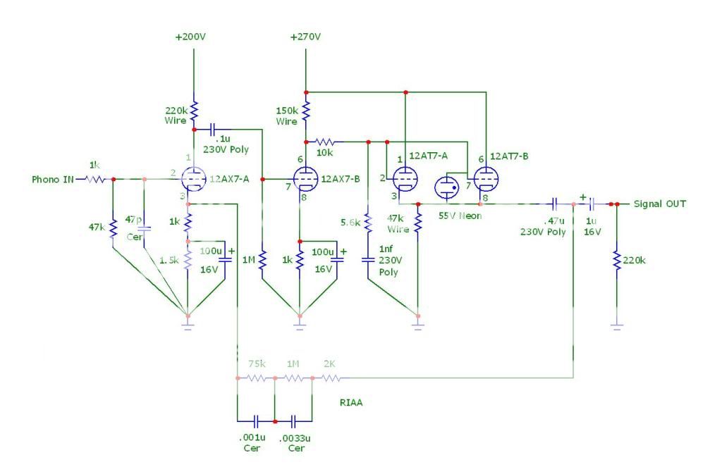
If anyone is interested here is the final schematic I have decided on. A few changes from the original Mcintosh however these are minor. Also the original schematic from Mcintosh had a few errors, like the polarity of the cathode caps on the first tube section. I have come to expect this from Mcintosh, a legacy of sorts.... All resistors were 1watt, mainly for wiring up convenience, also the breakdown voltage is better. All resistors are carbon except two plate and the CF resistor which are wire or metal film composition for better protection. I have found this pre-amp to sound very musical and airy, with surprising clarity despite the feedback RIAA. Distortion is assumed very low although I have no way to check this properly at the moment. If anything this sounds so linear as to appear as a well designed solid state preamp, no hum, hiss or annoying micro phonics. (possibly due to the tube shields). Thanks again everyone for the feedback, this has been a great learning experience. Feel free to make one yourself and comment on the sound
Last edited:
Hi Andreas
The real problem was an RCA cable layout problem, amplifiers and cable-coupling produced a self sustaining oscillator that oscillated at about 33kHz. The layout looked nice though, but since I was more than 3 years old at the time there was no way I could hear 33kHz, but the tweeters let the smoke out.
I'm really sorry to hear that and this is exactly why I think we should all collaborate and use LC/ST optical interconnects (think optical ethernet) for a raw analog transport.
Why can't we come up with an analog optical-based interconnect standard? maybe then it will finally satisfy the age old question of wether or not what exceptionally long line level cable will suit who's budget and the poorest of the people on this blue ball can have the best sounding cables, to end all arguments, and if an improvement is made later down the track then the parts which make up each end can be swapped out for newer ones.
Analog audio over LC/ST connectors sounds like a wet dream to me, slap a couple of diodes on either end, modulate them the right way with ultra low noise op amps, power it from battery, walla, hifi analog interconnect.
Where do we cut the response? at 25kHz? that will let the 19kHz FM sub carrier through. Kids can hear that, but grownups can't. Kids complain, and parents are dumbfounded. It happened to me. Not only did I have amplifiers that oscillated, I also had maladjusted FM receivers that let the smoke out of my tweeters.
We really should have 1MHz A/D converters permanently connected to the speaker terminals. The A/D output signals an Iphone APP that warns people that they are about to be smothered by smoke from burning speakers.
I believe the best way is to check the outputs with an oscilloscope to see if anything could go wrong. Because if anything can go wrong it will with teenagers around. Fortunately they are all gone by now and they have to struggle with their own I-phone APPs.
Why not just use a frequency counter and keep it turned on in the same room as your amp while listening?, if it registers anything in the RF range that you might suspect then shut everything down.
To me, from an engineers perspective, I find it rather silly to take low level signals out of a source through an obsolete RCA connector and then carry them over long lengths of shielded (because it needs it) copper wire to another obsolete RCA connector.
Sure, it might be the worlds most common connector, but can't we improve upon this with a futuristic optical analog interconnect? We are supposed to be living in the future afterall, no point in relying anymore upon a connector that was made in the 1940s and designed for commercial equipment.
We need something open source, so that it can propagate and dominate the entire industry, once and for all (for at least a few decades more hopefully.)
Last edited:
I'm really sorry to hear that and this is exactly why I think we should all collaborate and use LC/ST optical interconnects (think optical ethernet) for a raw analog transport.
Why can't we come up with an analog optical-based interconnect standard? maybe then it will finally satisfy the age old question of wether or not what exceptionally long line level cable will suit who's budget and the poorest of the people on this blue ball can have the best sounding cables, to end all arguments, and if an improvement is made later down the track then the parts which make up each end can be swapped out for newer ones.
Analog audio over LC/ST connectors sounds like a wet dream to me, slap a couple of diodes on either end, modulate them the right way with ultra low noise op amps, power it from battery, walla, hifi analog interconnect.
Why not just use a frequency counter and keep it turned on in the same room as your amp while listening?, if it registers anything in the RF range that you might suspect then shut everything down.
To me, from an engineers perspective, I find it rather silly to take low level signals out of a source through an obsolete RCA connector and then carry them over long lengths of shielded (because it needs it) copper wire to another obsolete RCA connector.
Sure, it might be the worlds most common connector, but can't we improve upon this with a futuristic optical analog interconnect? We are supposed to be living in the future afterall, no point in relying anymore upon a connector that was made in the 1940s and designed for commercial equipment.
We need something open source, so that it can propagate and dominate the entire industry, once and for all (for at least a few decades more hopefully.)
How would you modulate the audio? light intensity (amplitude modulation) would suffer long distance degradation even if you used a broad spectrum light source to get the frequency response. Also there would surely be interaction and degradation in every bend or imperfection of the cable. And don't get me started on stereo over one cable let alone 5.1 or 7.1 however I am genuinely interested to know your thoughts on this......
How would you modulate the audio? light intensity (amplitude modulation) would suffer long distance degradation even if you used a broad spectrum light source to get the frequency response. Also there would surely be interaction and degradation in every bend or imperfection of the cable. And don't get me started on stereo over one cable let alone 5.1 or 7.1 however I am genuinely interested to know your thoughts on this......
Its as simple as this
ST connectors are two fiber optic cables, there is your two mono channels.
Then invert the signal /before/ you modulate your laser diode /before/ it is put into the fiber optic cable. So on quiet passages the light travelling over the fiber optic cable is strong and bright, That solves your long distance issue (you might notice some loss over long distances with loud passages of music but it would have to be an extremely long cable)
Make sure you upright the signal before passing it through to a tube.
Modulating the laser diode through current control, would imho be best, which also ironically works out to be the ideal output of a TDA1541A...
Its either that or generating a carrier wave from a laser and then modulating it with a LCD panel by interfering with the laser beam and modulating it based upon the level of darkness of the LCD, like how they do in projectors to produce an image on a great big screen, but I suspect this would require quite a complex optical system.
Last edited:
Interesting idea, however the differences in wavelength will travel through the cable differently, some with less loss than others. Like I said some light will arrive at different times due to refraction indices. I can't help but think once you use an analogue audio signal to modulate a light wave and back again you might as well use a digital solution......but who knows. do it and let me know.Its as simple as this
ST connectors are two fiber optic cables, there is your two mono channels.
Then invert the signal /before/ you modulate your laser diode /before/ it is put into the fiber optic cable. So on quiet passages the light travelling over the fiber optic cable is strong and bright, That solves your long distance issue (you might notice some loss over long distances with loud passages of music but it would have to be an extremely long cable)
Make sure you upright the signal before passing it through to a tube.
Its either that or generating a carrier wave from a laser and then modulating it with a LCD panel by using interference patterns, like how they do in projectors to produce an image on a great big screen, but I suspect this would require quite a complex optical system.
Interesting idea, however the differences in wavelength will travel through the cable differently, some with less loss than others. Like I said some light will arrive at different times due to refraction indices. I can't help but think once you use an analogue audio signal to modulate a light wave and back again you might as well use a digital solution......but who knows. do it and let me know.
Yes, maybe someday, I'm too dumb to do it now, its something I've been wondering about for years.
http://www.skatelescope.org/public/... Technology for Astronomy Instrumentation.pdf
A lot of scientific institutions seem to be using analog optical interconnects right now for a wide variety of purposes from particle accelerators to astronomy. for 60GHz and beyond according to that paper, with noise levels of -168dB.
All we really need is a couple of cheap but good quality laser diodes, some detectors, and a way to modulate the current on the TX side and convert that current modulation back into voltage on the other end.
I can't really do it in Australia as Lasers are banned here (for consumers, aside from little 10mW ones) and I cannot get them past customs, otherwise I would've done this a long time ago.
I also don't have the equipment to test its linearity/bandwidth/noise levels.
The only thing I can do is prototype one based upon the cheap and readily available TOSLINK connectors, with a couple of op amps, an inverter, a way to convert volts into current, and walla, done.
Famous last words.
Last edited:
- Status
- This old topic is closed. If you want to reopen this topic, contact a moderator using the "Report Post" button.
- Home
- Amplifiers
- Tubes / Valves
- Glowing Plates of Doom