-------------------------------------that amp needs something as extended rework
try to find Ongaku schematic and compare general principle
problem is that - if you decrease voltage for SRPP - stage will not have enough headroom for driving 211 ; without thorough analysis I can't say more and I'm sorta short in time these days .......
one thing is sure - if you do what I wrote regarding additional xformer , heaters will be where they need to be
hello,
is it discuss for kondo ongaku? internet circuit had little mistake.
thx

Last edited:
Hi, wanted to update a bit on configurations I tried and my findings.
I always kept one of the mono-blocks unchanged to have a clear comparison.
First I built a mu-stage with 5687 and D3a; this was very clear improvement over my original 3 stage design; much less gain (but almost enough for my setup) and way more transparent; thanks to Kevin to steer me from 3 to 2 stage concept!
Then I tried an interstage design using 5687 driver (180V@15mA), Lundahl LL1692 wired 4:3.5 and this was another improvement over mu-stage design; it just sounded cleaner.
Here Tungsol 5687 sounds a bit better (smoother in a good way) in my system then RCA.
Next I tried Amperex 7788 wired as triode (190V@20mA), IT wired 3.5:2; here overall gain was perfect in my system, but 5687 setup sounded better; 7788 had more pronounced HF, but sounded sort of "sharp"; maybe I had some parasitic oscillations, but was not able to find any on my scope?
Next was D3a as triode (150V@19mA), IT wired 3.5:2; I find this slightly better then 5687, but difference is very small. With D3a speaker appears to be "bigger, wider", but sounds a bit darker. 5687 has a bit more detail, but it sounds "closer and smaller".
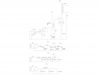
See attached my latest schematics with D3a driver and 3.5:2 IT.
When looking on the scope at 1K sine wave I get 150Vpp max at plate of D3a before there is a clipping (only on one peak of the wave) at the secondary of 3.5:2 IT transformer/211 grid; with 5687 I get 170Vpp max before clipping at secondary of 4:3.5 IT transformer/211 grid.
In both cases there is no clipping at D3a or 5687 plate/IT primary, even when pushed up to 200Vpp!? Wondering if that means that it is IT that distorts the signal?
In any case, this happens at higher input signal then I would have (I got 2.4Vpp from my transformer coupled DAC chip), but would be interested to understand the cause of that distortion.
I still got C3g and WE396(would use this one in parallel configuration) tubes to try as a driver; will report once I get a chance to compare them to D3a and 5687.
I always kept one of the mono-blocks unchanged to have a clear comparison.
First I built a mu-stage with 5687 and D3a; this was very clear improvement over my original 3 stage design; much less gain (but almost enough for my setup) and way more transparent; thanks to Kevin to steer me from 3 to 2 stage concept!
Then I tried an interstage design using 5687 driver (180V@15mA), Lundahl LL1692 wired 4:3.5 and this was another improvement over mu-stage design; it just sounded cleaner.
Here Tungsol 5687 sounds a bit better (smoother in a good way) in my system then RCA.
Next I tried Amperex 7788 wired as triode (190V@20mA), IT wired 3.5:2; here overall gain was perfect in my system, but 5687 setup sounded better; 7788 had more pronounced HF, but sounded sort of "sharp"; maybe I had some parasitic oscillations, but was not able to find any on my scope?
Next was D3a as triode (150V@19mA), IT wired 3.5:2; I find this slightly better then 5687, but difference is very small. With D3a speaker appears to be "bigger, wider", but sounds a bit darker. 5687 has a bit more detail, but it sounds "closer and smaller".
See attached my latest schematics with D3a driver and 3.5:2 IT.
When looking on the scope at 1K sine wave I get 150Vpp max at plate of D3a before there is a clipping (only on one peak of the wave) at the secondary of 3.5:2 IT transformer/211 grid; with 5687 I get 170Vpp max before clipping at secondary of 4:3.5 IT transformer/211 grid.
In both cases there is no clipping at D3a or 5687 plate/IT primary, even when pushed up to 200Vpp!? Wondering if that means that it is IT that distorts the signal?
In any case, this happens at higher input signal then I would have (I got 2.4Vpp from my transformer coupled DAC chip), but would be interested to understand the cause of that distortion.
I still got C3g and WE396(would use this one in parallel configuration) tubes to try as a driver; will report once I get a chance to compare them to D3a and 5687.
Attachments
... D3a driver and 3.5:2 IT.
When looking on the scope at 1K sine wave I get 150Vpp max at plate of D3a before there is a clipping
1.) IMHO 19mA too much.
2.) My D3a drivers (green LED bias -1.95...2V-, 170..175V cathode-anode voltage, 10mA anode current, cascode -DN2540- CCS, capacitor coupling to next stage) produces even 300Vpp with moderate distortion.
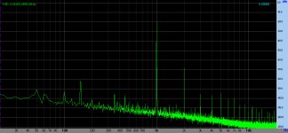
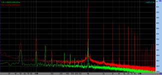
Measured FFT samples: D3a drives A2 mode 300B -8W SET- with 95V RMS, and 10W with 105V RMS.
Attachments
Hi, yes, it must have been a grid current. Without 211 tube I got 230Vpp on 5687 plate/200Vpp on 4:3.5 IT secondary without any visible sin wave distortion; was not able to try beyond that as I ran out of input signal voltage!
With D3a visible wave distortion happened at 200Vpp on plate/130Vpp on 3.5:2 IT secondary; here it was clear it had to do with not enough D3a grid bias as signal at that point was 2.8Vpp, so a limit for my -1.5V bias.
Will try a bit higher bias and lower current, as euro21 suggested.
With D3a visible wave distortion happened at 200Vpp on plate/130Vpp on 3.5:2 IT secondary; here it was clear it had to do with not enough D3a grid bias as signal at that point was 2.8Vpp, so a limit for my -1.5V bias.
Will try a bit higher bias and lower current, as euro21 suggested.
Hi, did some more testing and got a clear picture what is happening:
D3a: 208V plate,-2.3 bias, 19mA, measured gain-71 I get visible distortion on 211 grid (211 operating) at 160Vpp 3.5:2 IT primary/ 98Vpp on sec. (211 grid), 211 bias -50V
D3a: 175V plate,-1.9 bias, 16mA, measured gain-75 I get visible distortion on 211 grid at 160Vpp 3.5:2 IT primary/ 98Vpp on sec. (211 grid), 211 bias -50V
So, this two operating points give exactly same results, accept gain being a bit higher at second case (find this strange as expected gain to drop a bit with lower current)!
The second case looks good as it is ran more conservative and also G2 is under max spec that is 180V, so will leave it this way.
Then changed 211 bias from -50 to -55 (drops 211 current from 65 to 60mA); hear I was able to get up to 185Vpp 3.5:2 IT primary/ 105Vpp on sec.; so clearly distortion is caused by 211 grid current, as Kevin suggested.
Interesting was the test of Amperex 7788: 172V plate,-2.6 bias, 21.6mA, measured gain-54 I get visible distortion on 211 grid at 162Vpp 3.5:2 IT primary/ 92Vpp on sec. (211 grid), 211 bias -50V; so 7788 in same conditions distorts earlier then D3a, although I was expecting 7788 would be able to handle more grid current (lower plate impedance and ran at higher current)!
Tested also 5687: 190V plate,-7.5 bias, 15.5mA, measured gain-16 I get visible distortion on 211 grid (211 operating) at 120Vpp 4:3.5 IT primary/ 105Vpp on sec. (211 grid), 211 bias -55V; so 5687 trough 4:3.5 IT can deliver exactly same max Vpp to 211 grid as D3a does trough 3.5:2 IT; was surprised a bit here as I expected D3a in combination with step-down IT to be able to deliver more current and Vpp to 211 grid.
Based on this it seems it would be best increase plate V for 211 (it is 930V-970V now, depending on my mains voltage fluctuation) to around 1100V and then be able to run higher 211 bias voltage while maintaining 60-70mA current.
Running -50V bias and swinging +49Vpk implies you are extremely close to zero bias in the 211 and I would expect some grid current to be flowing under these conditions.
One quick question, how are you biasing the D3A? Are you using grid bias, an LED or something else?
A quick look at a grid current graph indicates that grid current should be about 8mA at +25V (for a wide range of plate voltage) so something is not adding up.. (Maybe just in my head..)
What is the dcr of the IT secondary, and what is the AC+DC component actually on the grid? Is the swing symmetrical about the baseline dc?
How do you return the cold end (AC wise) of the IT to signal ground?
Can you post pix or crude drawing of waveforms with amplitude? Circuit topology?
One quick question, how are you biasing the D3A? Are you using grid bias, an LED or something else?
A quick look at a grid current graph indicates that grid current should be about 8mA at +25V (for a wide range of plate voltage) so something is not adding up.. (Maybe just in my head..
)What is the dcr of the IT secondary, and what is the AC+DC component actually on the grid? Is the swing symmetrical about the baseline dc?
How do you return the cold end (AC wise) of the IT to signal ground?
Can you post pix or crude drawing of waveforms with amplitude? Circuit topology?
Here is the schematics of latest setup; see attached.
I am using just a 120R resistor on cathode; as this amp is not used below 80Hz I did not add bypass cap; measured -3db point is just under 30Hz without the cap.
I want to try battery bias (in series with the D3a grid), but choice of voltages are a bit limiting; button batteries seem to come in 1.55 or next is 3V.
IT, when wired 3.5:2 got primary DCR 790R, secondary is 200R.
From cold end of IT there is a 100K resistor, to the wiper of 20K bias adjustment pot, and there it is de-coupled to the ground.
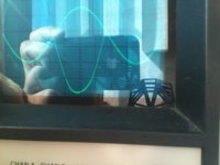
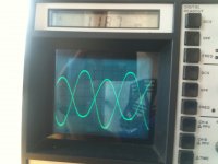
Here is the waveform; sorry for really bad photo, but you could see the distortion that starts to happen at the bottom; it is not symmetrical; top stays clean.
This is happening with 211 operating, measurement taken at 211 grid, 211 running at -50V bias and AC on 211 grid is about +49 Vpeak (98Vpp) when this distortion starts.
Second trace is on the input signal taken on D3a grid resistor; of course they are in different volt/divisions settings.
Yes, 211 data shows that at +25V grid there should be 8mA grid current.
How much current should I expect to be able to get out of D3a; 8mA trough 3.5:2 IT should result at just 4.5mA on D3a plate?
I am using just a 120R resistor on cathode; as this amp is not used below 80Hz I did not add bypass cap; measured -3db point is just under 30Hz without the cap.
I want to try battery bias (in series with the D3a grid), but choice of voltages are a bit limiting; button batteries seem to come in 1.55 or next is 3V.
IT, when wired 3.5:2 got primary DCR 790R, secondary is 200R.
From cold end of IT there is a 100K resistor, to the wiper of 20K bias adjustment pot, and there it is de-coupled to the ground.
Here is the waveform; sorry for really bad photo, but you could see the distortion that starts to happen at the bottom; it is not symmetrical; top stays clean.
This is happening with 211 operating, measurement taken at 211 grid, 211 running at -50V bias and AC on 211 grid is about +49 Vpeak (98Vpp) when this distortion starts.
Second trace is on the input signal taken on D3a grid resistor; of course they are in different volt/divisions settings.
Yes, 211 data shows that at +25V grid there should be 8mA grid current.
How much current should I expect to be able to get out of D3a; 8mA trough 3.5:2 IT should result at just 4.5mA on D3a plate?
Attachments
I'd try a cheap red LED as the current 120 ohm resistor is raising effective rp to something over 10K which is not good for linearity with the IT.
In addition you are throwing away about 13% of your available mu which means for a given output level you have to drive the D3A harder which is pushing it towards grid current and linearity issues. I suspect this contributes to the lack of linearity as you drive the D3A towards the saturation region. (Unnecessarily early onset)
I would expect the D3A to be able to source at least 3 - 4mA current before clipping.
I think you may find that there is significantly more drive available with fixed bias or the led than with the unbypassed cathode resistor.
Hi, will try eliminating cathode resistor and compare the result; I do not have a suitable LED at home, but got a 1.55V battery; will connect that in line with the D3a grid, bypassed with 0.01uF cap and 10M resistor, all ahead of grid resistor.
Cathode can then be connected straight to ground.
I seen this method used/recommended by Thorsten, so will give it a try:
"As it happens, our/my “ultimate” version of this concept also uses grid battery biasing (just measure the voltage across the cathode R – I have no notes left – and put suitable batteries in series with the grid, cathode straight to ground. Bypass the battery stack (Lithium Type Coin Cells is what I use) with a silver mica cap of at least 10nF and a 4.7 … 22MOhm resistor.(This is) - not very common because people believe if it is in series with the grid; it is “in the signal path” and if it is in series with the cathode it is not “in the signal path”. So they stick a big, bad, nonlinear rechargeable Nicad Battery in the cathode, where it is exposed to a lot of varying current so this non-linearity can be injected into the input voltage loop (grid to “ground”) and amplified and they are pleased as punch with themselves for having eliminated another evil capacitor ;-).
Instead they could have placed a nice linear primary cell (non-rechargable – lithium is best IMNSHO) in series with the grid, where there is practically no current flow at all (DC and AC will be in nanoampere region, if any) and eliminating any battery discharge noise needs a very small value capacitor...
Keep the 1K Gridstopper as close to the actual gridpin of the 7119. Obviously, negative pole from the battery to grid. Consider using lithium button cells, they have very little added stray capacitance (small size) and will last many years in this application, the ones for LCD wrist watches."
One other interesting detail I noticed: in my original, 3 stage configuration there was a rather large, 10K grid resistor on 211 tube; thinking about it, this would automatically adjust grid voltage as soon as 211 would start to drow grid current; for example at +25V peak 211 would want to draw 8mA grid current, but 10K resistor would right away cause voltage drop till grid is at 0 again and no current flows...
When I changed from original cap coupled to IT coupled driver I eliminated this grid stopper, so now 211 can draw grid current.
I guess, this "current restricting" grid resistor would basically also introduce distortion, so a better way should be to stay without it, but try to get D3a to deliver some grid current when needed. Hopefully removing cathode resistor from D3a, as you suggested would help; will report my findings.
Looking forward to hearing how you make out. I often use batteries for fixed bias where conveniently applicable. The series grid battery should be fine with a bypass. (See my Muscovite thread for an example of a phono stage with multiple stages using battery bias of various sorts.)
Hi, so did change D3a from cathode resistor to battery grid bias, operating at 155V on plate, -1.6V bias (silver oxide battery bypassed with .1uF cap and 10M resistor.
Got actually the same result; distortion of sine wave would happen at about 177Vpp on IT primary / 100Vpp on the 211 grid; 211 bias at -52V; so, just where 211 starts to draw small grid current wave would distort.
One difference with this setup now is that D3a running at less bias starts to distort at around 220Vpp on plate as this is where signal reaches 3Vpp, so it gets D3a grid into positive.
It is nice and easy to see where distortion comes from as it influences opposite peak then on I see on IT secondary.
Then I de-coupled cold end of the IT secondary directly to ground with 50uF cap; prior to that there was a 100K resistor plus part of 20K bias trimming pot between IT secondary and bias decoupling cap.
This change cleaned completely this distortion on secondary and now I can get clean wave up to 220V on primary / 125Vpp on IT secondary (211 grid); this D3a starts to distort as signal starts running it’s grid into positive (I wish one could find button battery with around 2-2.5V; all I found is either silver oxide 1.55V or Li-poly at 3V).
Then, I replaced 50uF cap with 0.47uF and got actually the same result as with 50uF cap; tried at both, 1000Hz and 100Hz sine wave.
I guess, once 211 starts to draw grid current this cap by-passes AC signal to ground which would, with no cap, have to pass through roughly 110K to ground (100K resistor and part of bias pot).
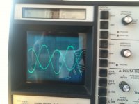
I attached 2 photos, one of wave distortion without this cap (you can see the bottom of the sine wave in the middle that starts distorting; this is on the IT secondary. Vpp is read at this point) and second one with the cap (you can see distortion now happens at higher Vpp and it happens first on IT primary (top of the wave left of the middle); bottom section of the wave on secondary that distorted previously stays clean!
What I am wondering is if there are any negative effects of adding this cap; it is strange that I cannot find this in any IT coupled schematics with fixed bias that I looked at. Usually there is just a large resistor from cold end of IT to negative bias supply; same as I had originally?
I guess, this works well as long as power tube does not draw any grid current; as soon as this happens there is a voltage drop over resistor between negative supply and IT, preventing grid current to flow.
As well, what would be correct way to size this capacitor; I guess the load this cap “sees” is resistance between IT secondary to ground, so around 110K in my case.
So, 0.47uF would give -3db at below around 3Hz; would this be the correct way to size this cap?
Got actually the same result; distortion of sine wave would happen at about 177Vpp on IT primary / 100Vpp on the 211 grid; 211 bias at -52V; so, just where 211 starts to draw small grid current wave would distort.
One difference with this setup now is that D3a running at less bias starts to distort at around 220Vpp on plate as this is where signal reaches 3Vpp, so it gets D3a grid into positive.
It is nice and easy to see where distortion comes from as it influences opposite peak then on I see on IT secondary.
Then I de-coupled cold end of the IT secondary directly to ground with 50uF cap; prior to that there was a 100K resistor plus part of 20K bias trimming pot between IT secondary and bias decoupling cap.
This change cleaned completely this distortion on secondary and now I can get clean wave up to 220V on primary / 125Vpp on IT secondary (211 grid); this D3a starts to distort as signal starts running it’s grid into positive (I wish one could find button battery with around 2-2.5V; all I found is either silver oxide 1.55V or Li-poly at 3V).
Then, I replaced 50uF cap with 0.47uF and got actually the same result as with 50uF cap; tried at both, 1000Hz and 100Hz sine wave.
I guess, once 211 starts to draw grid current this cap by-passes AC signal to ground which would, with no cap, have to pass through roughly 110K to ground (100K resistor and part of bias pot).
I attached 2 photos, one of wave distortion without this cap (you can see the bottom of the sine wave in the middle that starts distorting; this is on the IT secondary. Vpp is read at this point) and second one with the cap (you can see distortion now happens at higher Vpp and it happens first on IT primary (top of the wave left of the middle); bottom section of the wave on secondary that distorted previously stays clean!
What I am wondering is if there are any negative effects of adding this cap; it is strange that I cannot find this in any IT coupled schematics with fixed bias that I looked at. Usually there is just a large resistor from cold end of IT to negative bias supply; same as I had originally?
I guess, this works well as long as power tube does not draw any grid current; as soon as this happens there is a voltage drop over resistor between negative supply and IT, preventing grid current to flow.
As well, what would be correct way to size this capacitor; I guess the load this cap “sees” is resistance between IT secondary to ground, so around 110K in my case.
So, 0.47uF would give -3db at below around 3Hz; would this be the correct way to size this cap?
Attachments
Need to change out that grid resistor and bias pot, and use a much bigger cap as a consequence.. You want a the lowest possible DCR on the cold end of the IT since you are running into A2. I would switch to a 2K/2W pot running >10mA.. Cold end 4.3K, not sure what your bias supply is but hot end should be around -63V... Use large film cap from wiper to ground, no series resistor.
Possibly better use a small P type power mosfet as a source follower to buffer the current pot and drive the cold end of the IT with the source. This will allow for significant grid current to flow in the secondary of the IT without shifting the bias..
Possibly better use a small P type power mosfet as a source follower to buffer the current pot and drive the cold end of the IT with the source. This will allow for significant grid current to flow in the secondary of the IT without shifting the bias..
Hi, here is the complete schematics, including PS. You will notice some extra resistors in negative supply; this is leftover from previous configuration when this was also negative rail supply for SRPP driver when amp was configured as 3 stage.
I understand your point of redesigning bias supply so that it can provide more current in order to run 211 into A2.
One point I really wonder; would I actually benefit to redesign the amp be able to run into A2?
Since I got around 100db efficient speakers I don’t really need much power; sound quality and low distortion would be my main priority.
Considering this, would it be a better approach to increase the B+ on 211 a bit so I can operate 211 at same current (around 65mA), with >60V bias (I now get 65mA with -52V bias.
This would allow 120Vpp swing on the IT secondary before grid starts drawing current; with 3.5:2 IT this makes 210Vpp on the D3a plate; just about where D3a starts to clip with -1.6V bias.
With my 20K:8ohm OPT I should be able to get about 4.5W in class A1; this should give me enough headroom in my setup.
I would really like to hear your opinion on whether there is a real benefit in redesigning bias supply so it can handle some A2 operation?
I guess that current configuration with 100K resistor between the wiper and IT would have a benefit of isolating any bias PS noise; of course, as long as there is no grid current present?
Attachments
Hi, I did few more changes/tests and found following:
Increased bias supply current to 15mA, but seen no difference as long as I stayed in class A1.
Tested following driver’s, IT 4:3.5 coupled to 211, all at same 211 operating point (950V on plate, 64mA and -52V bias) and measured THD at 1Khz on OPT secondary at 1W into 5.7ohm load:
D3a (as triode), 170V on plate, 19mA, -1.6V battery bias; 0.4% THD – this sounded nice, but a bit bright, maybe a touch “harsh” compared to others
5687, 175V on plate, 19.5mA, -6.4V battery bias, 0.16%THD – this is very nice, very smooth, but maybe lacks a touch in HF extension
2C51, both sections in parallel, 165V on plate, 7.5mA/per section, 15mA total, -2.2V bias (regular cathode resistor with 200uF bypass), 0.3%THD – this is actually sounds best to me, sort of between 5687 and D3a
C3g (as triode), 210V on plate, 15mA, -3.2V battery bias, 0.7% THD – did not listen to this as was surprised with high measured THD; maybe it would get less if I would let the tube heat up longer (I did this test after about 10 min from turning C3g on?)
One thing that really surprised me was behavior I seen in my Lundahl OPT; with the same 2C51 tube I would get following THD, all at 1W, 5.7ohm load:
40Hz – 0.4%
100Hz – 0.31%
1KHz – 0.31%
2KHz – 0.37%
4KHz – 0.55%
6KHz – 0.77%
8KHz – 0.98%
10KHz – 1.2%
12KHz – 1.33%
14KHz – 1.37%
16KHz – 1.34%
18KHz – 1.17%
Then I did vey same measurement with Chinese made transformers that came with amp originally and got higher distortion (around 0.7% at 1KHz), but it would remain consistent with frequency (getting higher once you go below 200Hz).
Would anyone have idea why is Lundahl distortion is rising at higher frequency while it is much lower below 2KHz; would this be the function on higher primary (20K vs 10K for Chinese OPT)?
Lundahl has higher inter-winding capacitance which makes it roll-off earlier at HF; but would this influence distortion?
- Status
- This old topic is closed. If you want to reopen this topic, contact a moderator using the "Report Post" button.
- Home
- Amplifiers
- Tubes / Valves
- 211 amp SRPP driver