Hi, I got a Chinese built 211 SE amp that uses 5687 SRPP as a driver. I always used same Philips 5687 for past 5 years and never had any problems. Recently tried Tung Sol and had one fail soon with loud cracking sound. After looking into the shematics I got from the manufacturer I noticed that heater to cathode voltage is MUCH higher then max spec from 5687 tube data (roughly 160V vs 100V in the spec)! What is strange is that I used same Phillips tubes for 5 years with no problem.
Any way, I am now wondering about the best aproach. One simple possible solution would be lovering voltage drop accros the 5687 SRPP by bringing the top plate voltage down to, let's say 230V and bottom cathode up to -80v; this would make top cathode be around 80v so both would sit confortably within +/-100V max spec for heater to cathode.
What I am not sure is how would this effect the actual circuit and ability to drive 211 tube.
As I already did lots of modifications on this amp I am ready to go much further and redesign second stage if there would be a better solution sugested; even using an IT would be not out of question.
Please have a look at attached shematics; any sugestions are welcome!
Attachments
The heating circuit is there in the PS part; you will note 3.15-0-3.15 on the transformer secondary; it is simple 6.3V ac with centar grounded center tap.
Whats the voltage,
Between the heater and ground?
Ie I guess the 3.15 0 3.15 powers the srpp and the EC88?
So what is the voltage between 0 and ground?
Regards
M. Gregg
Last edited:
sorry - didn't saw it
anyway - make resistor divider from +390V to gnd , made of 330K/1W connected to 390V and
82K (small resistor will suffice) to gnd , put 10uF/350V cap across lower resistor (82K) , and connect heating CT to dividing point
that way heaters will be elevated to some 75-80V , problem solved
anyway - make resistor divider from +390V to gnd , made of 330K/1W connected to 390V and
82K (small resistor will suffice) to gnd , put 10uF/350V cap across lower resistor (82K) , and connect heating CT to dividing point
that way heaters will be elevated to some 75-80V , problem solved
Yes, both input stages use comon heaters; center tap is grounded, so volatage between 0 and ground is 0V.
The problem with elevating heaters, as you sugest is following:
In SRPP stage the top cathode is at 160V, bottom cathode is at -150V!
This means, total difference between two cathodes in 5687 tube is 310v, basically making impossible to have less then 100V cathode to heater difference if keeping curent operating voltages for SRPP.
This is the reason I got really confused and am open in possible re-design, if necessary...
uff
forget everything I wrote above
doing several things in same time often doesn't help in seeing everything on schmtc ....
it seems that small additional xformer is must - having 2 windings , resulting that each small triode position is having dedicated heater winding
then - appropriate resistor divider nets for each one , putting fil of first stage to app. +50V , lower one in SRPP to some - 100V and upper one in SRPP to some +100V
having lower one SRPP triodes in one envelope , and upper one in another envelope is absolute must
Hi, no problem, thanks for trying to help!
The real problem here is that to SRPP stages are just 2 sections of same dual triode, 5687, so they share same heater....
This is why I am asking about advice on possibly droping the SRPP top plate voltage and rising the bottom cathode in order to get two cathodes at around +80v and -80v; heater at 0V should then work fine.
What I do not know and need a help with is how will this influence SRPP performance as a 211 driver?
Other option is to just keep running it vay over the spec using the Phillips 5687 tubes which somehow survived this for last 5 years....very strange as they are run over 60% higher then max spec...but they never had a problem...
that amp needs something as extended rework
try to find Ongaku schematic and compare general principle
problem is that - if you decrease voltage for SRPP - stage will not have enough headroom for driving 211 ; without thorough analysis I can't say more and I'm sorta short in time these days .......
one thing is sure - if you do what I wrote regarding additional xformer , heaters will be where they need to be
Hi, thanks, yes, that is what I was worried about.
Ongaku is using 6072 (12AY7) in SRPP configuration followed by a 5687 cathode follower driving a 211.
TriodeDick got a simple Mu Stage in his 2-stage 211 amp. Looks that would be easy enough to implement as I got needed voltages available.
Would need to chenge my input tube from e88CC to 27 and add transformer to suply 2.5 V filament for 27.
I alredy got some D3A tubes left from phono amp project, so that is a bonus.
If someone has other sugestion that could work fine, please let me know.
In particular, it would be great if I could keep existing 9 pin sockets...
A 76 would slot right into that TriodeDick circuit. My experience with the 27 has been variable - there are some good ones but an awful lot of them seem to be microphonic. The 56 is often regarded as being interchangeable with the 27 but actually has significantly higher mu. The major difference between the 56 and 76 is filament voltage, the 56 being 2.5V, and the 76 being 6.3V.
Note that the 27 has a mu of 9 vs mu of 13.8 for the 56/76.
I also recommend the 6C5 and 6J5 which with a mu of 20 should give you full output at a little under 2Vrms in.. Consider the 6FQ7/6CG7 if you want to stay with a 9 pin socket.
Note that the 27 has a mu of 9 vs mu of 13.8 for the 56/76.
I also recommend the 6C5 and 6J5 which with a mu of 20 should give you full output at a little under 2Vrms in.. Consider the 6FQ7/6CG7 if you want to stay with a 9 pin socket.
Hi Kevin, thanks a lot for sugestion, 6FQ7/6CG7 could work particulary well as I could stick to my alredy available two 9-pin sockets and just rewire them from my current circuit to TriodeDick Mu stage to convert curent 3 stage into 2 stage amp.
Other option will be to keep my 3 stages and reduce the voltage drop across my 5687 SRPP second stage in order to stay within Max heater to cahode voltage rating; I could get close to 400v drop across the SRPP (200v per section) that way; surently there is 575V drop. at the same time I could reduce the Rka and Rk resistors in SRPP to increse the current; with present 4.7K it is drawing only just above 3mA. Would going uo to usually sugested 10mA for 5687 tube be right and help keep the headroom?
Other option will be to keep my 3 stages and reduce the voltage drop across my 5687 SRPP second stage in order to stay within Max heater to cahode voltage rating; I could get close to 400v drop across the SRPP (200v per section) that way; surently there is 575V drop. at the same time I could reduce the Rka and Rk resistors in SRPP to increse the current; with present 4.7K it is drawing only just above 3mA. Would going uo to usually sugested 10mA for 5687 tube be right and help keep the headroom?
Yes, makes sense, going to 2 stage should be improvement, just would like to chek on few practical considerations:
Since there is aproximately 230V petential difference between two cathodes, I would probably hawe to add additional 6.3V transformer to stay within max heater-to-cathode voltage spec; in theory, if I use 6FQ7/6CG7 and elevate the heaters to 110V I would be RIGHT on the limit of max spec (100V above 6FQ6 cathode and 120V below D3a cathode), but I am not sure it is a good idea to be that close to the max. rating?
Looking at tube data it seems that 5687 could also work instead of 6FQ7; it has mu of 17. Reason for considering 5687 is that also fits 9 pin socket and I alredy got some tubes.
I noticed TriodeDick uses some pretty large capacitors (0.33uf, 1 uf and 2.2uf cupling capacitor) vs my current circuit using 0.1uf and 0.47uf; was wondring if it is really necessary to use this high values; would be nice to be able to use what I got. I am using my amp just above the 70Hz, so low end is not extension is not really a priority.
Hi enzoastro, just wanted to clarify your comment re. the e88cc plate voltage; this is actually a mistake on the schematics, 90v is actually measured at e88cc plate, there is approximately 115V on top of plate resistor. e88cc draws approximately 3mA current at idle.
Anyway, I guess I will be trying to adopt TriodeDick circuit, as suggested by Kevin, so my input stage would not be used.
If someone would have some more suggestions of adapting TriodeDick circuit to my amp would be great to hear; especially it would be great if I could make use of tubes I got on hand (e88cc, 5687) instead of changing the socket and looking for 27.
Thanks for any suggestions!
Or float,
with a 0.1uf polypropylene 600v from 0 to gnd.
The divider is better sometimes floating can overcome other problems.
Regards
M. Gregg
Which problems can be overcome by floating the heaters?
IT version
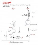
Hi Kevin, now, for some time I been using Triodedick circuit, but with 5687/D3a configuration. Was really please with performance, a clear improvement from my original 3 stage, SRPP driver configuration! Gain was JUST enough with my passive TVC as I got really sensitive speakers (around 100db).
Triodedick also suggested trying his latest, IT variation of the circuit, using IT instead of Mu-stage (see atached).
I got LL 1692/18ma transformer and am looking to try testing following tubes (got most of them already):
5687 at around 17mA/190Vp (8v bias)
5687 in parallel at around 10mA each/180Vp (8v bias) - (IT can handle up to 21mA if configured as 3.5 : 4
WE396a in parallel at 8mA each/150Vp (2v bias)
C3g (as triode) at around 14ma/190Vp (3v bias)
7788 (as triode) at around 18mA/190Vp (3v bias)
D3a (as triode) at around 20mA/160Vp (1.5v bias) – here I could use IT as a 3.5:2 step-down to further reduce impedance, but am worried about low bias that might result in input overload.
Both, my Phono and DAC sources are spec to output around 0.7 Vrms, so in theory a 3V bias on the input valve would give me 6db headroom; but not sure if that is a really necessary consideration?
I noticed two ways for connecting pentode as a triode:
1) g2 to anode and g3 to cathode
2) g2 and g3 to anode
Is one of those "right" or "better" or is it application dependant; what is the difference in performance?
Thanks for your comments, also any thoughts on the choice/application of drivers I am going to test?
Attachments
- Status
- This old topic is closed. If you want to reopen this topic, contact a moderator using the "Report Post" button.
- Home
- Amplifiers
- Tubes / Valves
- 211 amp SRPP driver