I recently received this article from the "Electronic Experimenter's Handbook". Written by Herbert I. Keroes of Acrosound, it details the building of a mono version of what is known as the Acro 20/20 amplifier. I'm sure this design could be bettered in many ways - notably that power supply! - so for historical purposes only. I've included the description of the schematic, not the construction notes.
So here is Mr. Kereos:
...snip...
So here is Mr. Kereos:
Years ago, before the hi-fi era, an audio power amplifier was built that sounded better than any other then in existence. This unit was called the Loftin-White amplifier, after its designers, and had many ingenious features. It used direct coupling and a method of bias stabilization that was probably the first application of inverse feedback in an audio amplifier. Overall, it had a distinctly better sound - noticeably reduced distortion and better bass response.
The modern theory of feedback amplifiers provides a ready explanation for the improvement brought about by the Loftin-White circuit. Direct coupling reduced the low-frequency attenuation and phase shift, and improved the stability of the amplifier as far as low-frequency transients were concerned. Today we know that an amplifier lacking low-frequency stability sounds weak and puny compared to one that is more stable but less powerful.
...snip...
How It Works:
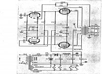
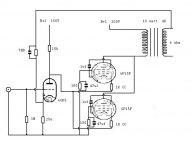
Input stage V1 is used as a combination voltage amplifier and phase inverter. This tube operates with "starved" plate current to achieve maximum amplification, a condition created by the 1-megohm plate resistors (R9 and R10). To obtain best linearity and maximum driving voltage, the heater of the tube is also "starved" by means of dropping resistor R15.
Direct coupling is used between V1 and the push-pull output tubes V2 and V3. The cathode current of each output tube flows through a separate resistor, R3 and R4 respectively, which is coupled to the corresponding grid of V1.
The current feedback through R3 and R4 accomplishes several purposes. First, it stabilizes the cathode current of each output tube under quiescent operating conditions. Secondly, the cathode current is also stabilized under dynamic operating conditions to a point where the stage operates almost completely as class A, resulting in minimum distortion. Finally, the stabilized direct coupling produces an amplifier which has only one principal source of low-frequency phase shift, output transformer T1; this provides perfect low-frequency stability.
In addition to the current feedback, 20db of voltage feedback is provided by the capacitor-resistor combination C6-R13. The voltage feedback circuit is connected between the secondary of T1 and the cathode of V1a.
Response of transformer T1 drops only 1db at 5cps and 60kc. The primary halves of T1 are tightly coupled for distortionless high-frequency performance. Ultralinear taps are provided at the optimum ratio for the output tube used.
Attachments
Last edited:
and a list of the parts:
C1,C2 = .047uf/600V
C3 = 250uf/6V
C4,C4 = 40uF/150V
C6 = 100uuf / 500V ceramic
C7a/C7b/C7c = 60/40/20uf / 450V with insulated mounting
C8 = 100uF/300V with insulated mounting
D1,D2 = Silicon Diode 750mA/600V PIV (IN1096 or equivalent)
F1 = 3A slow-blow
J1 = RCA jack
L1 = 2H/200mA filter choke
R1,R2,R7,R8,R9,R10 = 1M / .5W - 1% resistor
R3,R4 = 10-ohm / .5W, 1% resistor
R5 = 2200ohm / .5W, 10% resistor
R6 = 330ohm / .5W, 10% resistor
R11, R12 = 1500-ohm, 10W, 10% resistor
R13 = 5600-ohm, .5W, 10% resistor
R14 = 220kohm, .5W, 10% resistor
R15 = 6.8ohm, 1W, 10% resistor
R16 = 22ohm, 2W, 10% resistor
T1 = Output Transformer (Acrosound TO-370)
T2 = Power Transformer 185V/200mA and 6.3VCT/4.5A
V1 = 12AX7
V2, V3 = EL84
Not quite true that the OPT is the only principal source of LF phase shift. The output cathode decouplers will have a significant effect too at mid-LF, although this will eventually disappear at sufficiently low subsonic frequencies. C4/C5 combined with 1/gm and R11 etc. form a lead-lag network but because of the likely resistance ratios this could produce nearly 90 degrees of phase shift before levelling out again. A conventional output cathode decoupler has much less effect because the cathode resistor would be much smaller.
The accuracy of output bias will be similar to any other simple system which monitors cathode voltage - adequate but poorer than either normal cathode resistor bias or fixed grid voltage bias. This is because it corrects average current rather than quiescent current. The high cathode voltage, required by direct coupling, will reduce efficiency.
If the first stages anode loads (R9,R10) are high, then the phase splitter feedback resistors (R7,R8) would need to be even higher otherwise the advantage of a high anode load is thrown away. This could create a problem with Miller effect in the phase splitter, although the local feedback will compensate for this.
The OPT is clearly a high quality item, which is probably where most of the sound quality in this design comes from.
This design is a good example of how all electronic design involves compromises. It just happens to use different compromises from more conventional circuits.
That circuit looks very similar or the same as one I built from an Acrosound catalogue some years ago. I seem to remember the 1M's being 510K though.
I built it as a stereo amplifier and it took a lot of time and effort to get it conditionably stable in one channel. I used Dynaco Z-565 for the outputs. I asked around on the Joenet for advice / help and the general concensus was my opt was the issue, IOW it needed the Acro OPT.
I built it as a stereo amplifier and it took a lot of time and effort to get it conditionably stable in one channel. I used Dynaco Z-565 for the outputs. I asked around on the Joenet for advice / help and the general concensus was my opt was the issue, IOW it needed the Acro OPT.
A slightly cooler cathode can reduce the electronic grid current which appears when the grid is insufficiently negative. This could be an advantage if the valve is being run with a fairly low anode voltage (as it presumably it in this circuit). The same trick is sometimes used for thermionic diodes used in radio receiver AM detectors or noise limiters, which otherwise have a slightly negative 'turn-on' voltage.
Slightly reduced filament voltage in the 12AX7 also at least in some instances reduces certain types of tube generated noise. I think in this case though that the voltage drop is a little on the extreme side.
These amplifiers can sound pretty good - I had a loaner for a while.
Were I to build something similar I'd at least go with a full wave voltage doubler.
These amplifiers can sound pretty good - I had a loaner for a while.
Were I to build something similar I'd at least go with a full wave voltage doubler.
I have a single Acrosound "Stereo 20" (er, it's a monoblock!) waiting for a rebuild - the tube sockets mounted to the board are pretty shot and everything else is original. It still fires up but it's definitely not something I would want to run everyday. I have a feeling it will be a long time before I see another one crop up, but eventually I will have a nice pair for a vintage setup.
There was the Acrosound 2020 which was definitely stereo, I had one on loan for a short while.
I guess there must have been a mono version as well, I've only seen the stereo amp though..
The board quality in all Acrosound amps seemed to leave a lot to be desired. The 2020 sounded very good and surprisingly the Dyna ST-35 was not that far behind - I liked both of these better than Dyna ST-70 or MKIII.
It looks like there was a 20 mono amp, a 20A which could be powered off the 20(!), and the more famed 20/20.
Early stereo weirdness.
http://www.hifilit.com/hifilit/Acrosound/gold-1.jpg
Early stereo weirdness.
http://www.hifilit.com/hifilit/Acrosound/gold-1.jpg
Message for KStagger, ACRO 20 amp
Hello Kurt!! 10-9-12
The ACRO DC amp has some big problems in its design!! It begs us for a fix !
Keroes operated the 12AX7 starved, so there is only 75 VDC on the plate. This means that the 6BQ5 cathode gets biased at 88 VDC ( -13 VDC bias ) from a B+ supply putting 430 VDC on the 6BQ5 plate
Keroes ran 58.3 mA. through each 6BQ5, at 342 VDC P-K, so each 12 Watt rated plate is operating at (gasp) 19.93 Watts of dissipation.
A new 6BQ5 tube instantly degrades in the first hour on. Tube life is always problematical. Additionally, tubes are thermally STRESSED-sounding when operated over their maximum dissipation ( +174% ).
The Rk for each 6BQ5 is 1,500 Ohms, power-rated at FIVE Watts, and the 6BQ5 is biased 88 VDC above ground.
'Go figure that one out.....that is ( 88 VDC times .0583 A.) or 5.127 W. of continuous Rk dissipation. Needs to be, at a minimum, one Mills MRA-12, ( 12 Watts rated) if not two !!
To my knowledge, no one in audio in 50 years has ever analyzed, addressed and resolved these matters. I would like to offer people a good solution.
I have been working on paper, for over a week, redesigning the stock ACRO so good design compromises can be made, to a) re-configure the direct couple, and b) provide close to optimal operating points for both stages (simply by operating the tubes conservatively). I am fairly pleased with it, as it stands now. But I would really appreciate getting your opinion and input before going public.
The re-done circuit balances within a fraction of a volt everywhere, through resistor choices, which you will see. Its only 8 resistors and 5 caps per channel. If you will send me your email address please, mine is drlowmu - AT - gmail DOT com, I can send you my various schematics as PDF attachments. Thanks so much.
Sincerely,
Jeff Medwin, Warrensburg, MO
I would like to publish a guide for people to re-do these amps, in a
An unremarkable circuit. Paraphase splitter has low overall gain and poor balance (particularly at higher frequencies). Output stage sits on fat resistors, wasting power. NFB is limited by available gain.
Of course, since we aren't concerned with tube cost these days, and silicon rectifiers are free, a modern approach would use a negative supply rail, most likely for grid bias (drive the output stage through a voltage divider, yes you loose some gain, so what). A few extra stages keeps gain high while preserving balance; I might suggest a pentode front end (6AU6, etc.) driving an LTP. A triode-pentode can be used for the preamp, the other section being used for CCS duty for the LTP. For ridiculously high bandwidth (into the MHz) or class 2 operation, cathode or source followers can be added before the output tubes. The additional gain allows many feedback approaches; some shunt feedback on the output tubes will improve things without the OPT's phase shift affecting things. 30-40dB total should be easily achievable, resulting in very, very solid bass, easily beating the OPT into saturation at low frequencies and high levels (not that that's a goal or anything).
Direct coupled circuits have substantial benefits in bandwidth, besides bias stability completely independent of tube type (rolling, anyone?) and LF cutoff. The best Tektronix scope amps were of course DC coupled. It's very easy to make a high efficiency tube amp (not an oxymoron!) with class D switching techniques; switching speeds on the order of 100ns are easily achieved.
Tim
Hi Tim,
Nice post. I am really not trying to redesign the amplifier.
I think it is fairly simple design, which I like. It is easy to make a amp more complex, but it is not always a better result I have found.
What I want to do is to simply make appropriate operating point changes in both stages, so that the final tubes do not eat themselves up as they are now, while operating at 174 percent OVER their MAXIMUM rated plate dissipations !!
Why no one has intelligently (and conservatively) addressed this, in fifty years, is beyond my wildest comprehension.
I want to give ACRO 20-20 owners a very well thought out re-do path for increased reliability.
I have worked extensively with SE DC Loftin-White amps for five years now, and I can apply what I learned to help existing ACRO users. Why not ?? I enjoy it, it is fun to contemplate.
We can talk privately any time about how we each would each re-design the amp. Everyone has their "pet" circuits. For example, I am no fan of paraphase splitting, or negative feedback, or ultra non-linear pentode operation. But for now, I would like to stay on-topic with this thread. KISS rules !! Thanks so much for your very thoughtful post.
Jeff Medwin
Hi Tim,
Nice post. I am really not trying to redesign the amplifier.
I think it is fairly simple design, which I like. It is easy to make a amp more complex, but it is not always a better result I have found.
What I want to do is to simply make appropriate operating point changes in both stages, so that the final tubes do not eat themselves up as they are now, while operating at 174 percent OVER their MAXIMUM rated plate dissipations !!
Why no one has intelligently (and conservatively) addressed this, in fifty years, is beyond my wildest comprehension.
I want to give ACRO 20-20 owners a very well thought out re-do path for increased reliability.
I have worked extensively with SE DC Loftin-White amps for five years now, and I can apply what I learned to help existing ACRO users. Why not ?? I enjoy it, it is fun to contemplate.
We can talk privately any time about how we each would each re-design the amp. Everyone has their "pet" circuits. For example, I am no fan of paraphase splitting, or negative feedback, or ultra non-linear pentode operation. But for now, I would like to stay on-topic with this thread. KISS rules !! Thanks so much for your very thoughtful post.
Jeff Medwin
Its an interesting circuit, you don't see many DC coupled tube amps and the front stage of this guy is rather novel. Have you made much headway in optimizing this circuit? Does the front end really need to be run in starved plate mode, it seems like unnecessary compromise. I also think that an improved power supply, CCS and/or LED bias might bring this up another level.
Is it possible to add a mosfet/powerdrive stage to a DC coupled amp like this?
Hi,
Henry Platt and I have measured the stock amp's power supply fairly well. I have had someone working on getting push pull balance and inversion out of the 12AX7 front end stage, without it being too complex. He has almost finished that task.
We will likely propose new op points for the front end and finals stage, with a parts list, and schematic in the coming months. We can advantageously eliminate the series coupling caps on the input stage completely, so it will finally be a true DC amp, and run the 12AX7 halves in a conservative ( but not totally starved ) manner.
I want to combine reliability ( first ) and sonics and performance all into one package. Coming up soon.
Who wants to be one of two beta testers with their 20-20 ??
Jeff Medwin
ACRO 20-20 redo is designed
Hello everyone :
Its been six months since my last post on this amplifier design. I pretty much know what needs to be done by now to anyone's ACRO, to make the ACRO 20-20 more long-term reliable, and sound better.
Quality over quantity.
First, we must eliminate its out-of-time paraphase phase invertor.
Second, we need to lose its two coupling caps into the 12AX7 halves, ugh, series coupling caps - how performance robbing !!
Third, it needs to eliminate its pentode ultra-linear Finals operation, and be converted into a two stage all triode push pull amp, without any time-degrading feedback loops what so ever.
The 12AX7 sections should be configured as a simple differential amp, drawing no more than 1.2 mA. total, and it needs to directly drive the grids of the two Finals tubes, which should be triode-connected 6AQ5s ( better choice than EL84's, and reasonable in cost too ). Outputs must be rebiased so as not to be eating themselves - as does the stock configuration. The power transformer will operate cooler, longer, with less stress placed upon it.
Rebiasing will require a Mills MRA-12 cathode resistor ( Rk ) of about 6,000 Ohms for each output tube, instead of that silly 1,500 Ohm cathode resistor ( Rk ) as in the stock 20-20 and 20A monoblocks.
There are several other minor but very important details, and I don't have my design notes at hand.
I recently had such an amp circuit configured in my home from a 6BQ5 Heathkit, and it was very pleasing so I know people will flip over this.
NOTE : If anyone has an operating or non operating 20-20, or a pair of 20As they want to have redone in 2014, I'd consider doing this hands-on, gratis, just for the parts cost. ( As long as I can take photos of the changes, and document everything, so OTHERS can duplicate the modification. )
Contact me via email. I am in Missouri.
Jeff Medwin
Ouch ....
Having thought about this some as the well-argued previous posts deserved. But I cannot help seeing some priorities here with which I disagree. (By the way, DF96, there is yet another l.f. pole in the original schematic in C2.R2 - so the OPT is not nearly the only one.)
There seems to be a fixation with avoiding l.f. poles, at the expense of more important performance features. Yes, of course RC networks feature in stability considerations, but is it insurmountable with proper design? And modern capacitors are conveniently physically small to be practical. I have a tube amplifier with all of 3½ RC time constants apart from the OPT, with no problem effecting l.f. stability. (The 'half' time constant is a screen bypass going back to 0-phase at very l.f.! That actually helps with stability.)
'Time-degrading feedback loops'? Are we talking audio; is it about stability considerations at h.f.? Otherwise I fear I cannot see the concern - perhaps to broaden my horizons with an explanation?
Then, all data I ever found on the 'UL' topology appears favourable. It shows having 80% of usefull triode characteristics but with pentode output ability and improved efficiency. In my above mentioned 100W tube amplifier I would certainly have had some extra cost using triodes for a rather limited advantage. (Folks talk about 'half-pentode' performance - that is not true. Distortion and rp can be less than twice the triode figure, with limited additional third order - but I am getting off-topic.)
Coupling caps 'performance robbing'? Again depending; I seem to get 90W over a 30Hz - 18kHz band, with a 10W output over 6Hz - 70kHz. The phase shift is within some 4 degrees from 15Hz - 40kHz. (Just as illustration, no boasting intended. No very special measures involved.)
But back to the main aim of the original circuit: I fear I fail to find the necessity for all those measures (and compromises) simply to avoid another RC time constant. My bad?
- Status
- This old topic is closed. If you want to reopen this topic, contact a moderator using the "Report Post" button.
- Home
- Amplifiers
- Tubes / Valves
- Keroes: Direct-Coupled amplifier