Hey guys,
I recently ripped apart an old build, and now have a hammond 119DA spare... i was using it in an SE 1/4 watt application where it wasn't really used to its full potential, so my question is, what could i do with it? what tubes could i use it with? and what configuration?
I recently ripped apart an old build, and now have a hammond 119DA spare... i was using it in an SE 1/4 watt application where it wasn't really used to its full potential, so my question is, what could i do with it? what tubes could i use it with? and what configuration?
another twisted way to use this transformer is to tie the output in series to the negative feedback network and use the primary as a DI output (to pins 2&3 on a xlr connection)
if you need less voltage on the xlr, use the 4 ohm tap on the primary. If you still need more build an "O" type attenuator on the 600 ohm secondary (xlr side).
if you need less voltage on the xlr, use the 4 ohm tap on the primary. If you still need more build an "O" type attenuator on the 600 ohm secondary (xlr side).
Hmm, I think i would like to use as much of the 12 watt potential as i can, but i cant see an easy way of doing that. im thinking a push pull output between 2 cathode followers? but then whats an ideal output, 12BH7?
The idea of using it the other way for a line out is interesting, could do a better job at speaker emulation than a dummy load.
The idea of using it the other way for a line out is interesting, could do a better job at speaker emulation than a dummy load.
You could try something like I did here:
http://www.diyaudio.com/forums/tubes-valves/211352-new-amp-13de7-se-hybrid.html
http://www.diyaudio.com/forums/tubes-valves/211352-new-amp-13de7-se-hybrid.html

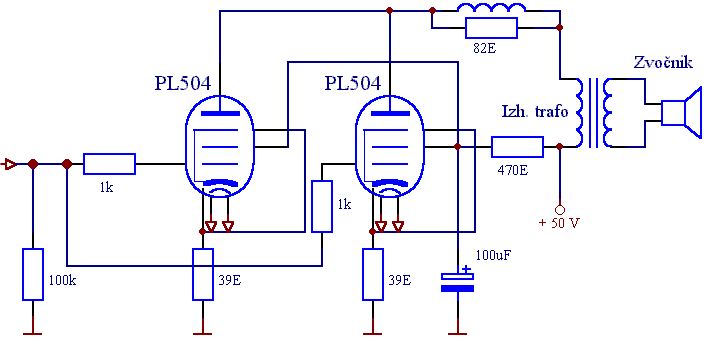
The audio transformer is 600-800/8 ohm 10W (600 ohm suggested)
L = 4-5 turns diam.0.5 mm around the 82 ohm 2W resistor.
Supply voltage: min 50Vcc - max 110Vcc (90V suggested)
Heaters voltage: min 24Vac/Vcc - Max 29Vac/Vcc (27V suggested)
Cathode resistors = 39 ohm 2W
Note: a bypass capacitance of 470uF 50V could be added in parallel to the cathode resistor of each tube.

Power supply for 50Vcc.
Last edited:
Before doing SE with DC biased transformer please answer the question: how big it is? 12W transformer for SE output looks in size like 50W power transformer. That's why I offered to use it for OTL, because I assumed that the transformer used for headphone amp can't be so big.
A circlotron might be worth consideration, but even then your primary impedance is too low for most small power valves. What's got an anode impedance of around 1k, and about the same power as an EL84?
Basically your options are limited because there's no gap and no centre tap. It's a speaker-matching transformer.
Basically your options are limited because there's no gap and no centre tap. It's a speaker-matching transformer.

The audio transformer is 600-800/8 ohm 10W (600 ohm suggested)
L = 4-5 turns diam.0.5 mm around the 82 ohm 2W resistor.
Supply voltage: min 50Vcc - max 110Vcc (90V suggested)
Heaters voltage: min 24Vac/Vcc - Max 29Vac/Vcc (27V suggested)
Cathode resistors = 39 ohm 2W
Note: a bypass capacitance of 470uF 50V could be added in parallel to the cathode resistor of each tube.

Power supply for 50Vcc.
Your posted circuit shows a typical single end transformer application. That little transformer is not designed for a DC bias current. It is designed for AC only, with a DC blocking capacitor. The magic smoke may escape as you have it shown.
DT
I didn't know it is a line transformer the one you want to use  .
.
In the schematic I posted, I specified "Audio Transformer", if you want to use a line transformer instead, you must use a 50VA transformer at least.
Also, a line transformer has very little inductance compared to an Audio transformer and this causes reduced bandwidth (poor at low frequencies)
If you need 6.3V for heaters you should use the EL504 (same as PL504 but 6.3V heater)
Last edited:
Thanks for the contributions guys, I didnt realise this wasn't intended for SE use, i think the MOSFET output idea is looking more ideal. Most OTL designs ive seen require alot of tubes and power for a fairly weak output, and i have tried to understand circlotrons, but the concept is still odd to me.
- Status
- This old topic is closed. If you want to reopen this topic, contact a moderator using the "Report Post" button.
- Home
- Amplifiers
- Tubes / Valves
- what to do with a 12W 600ohm to 4/8 ohm output transformer?