Dear all experts.
Recently I build up 300B Se Amp based on Yamamoto schematics following are part being using in this setup.
300B as power stage
Siemens C3M as drivers stage ( Pentode configuration )
Lundahl LL1664 100ma as Output Tran.
Power tran, get from vt4c (HK). 400v-0-400v
After finished & power up. doesn't work up well at all. After measuring the voltage of the system, noticed the c3m plate voltage drop to 10v after few second. But the rest of the measurement point still OK.
Some debugging status.
Disconnected driver stage to output stage. c3m VOLTAGE also drop.
Plug in my c3m tube to my friend Yamamoto system. work well to confirm c3m still GOOD.
Measuring the c3m bias voltage, look WELL.
Now I really out of idea what going wrong. is it possible tube socket problem or others. Need advises from the diyers...
Thanks in advance.

well the first thing to do is to check the connections. its common for people to get turned around on the pin number on the tube socket. The second thing you have to double check is the tube pin out with the data sheet. common typos that happen with prints is the mislabeling of pin numbers on vacuum tubes.
Thanks for reply, I had checked the pin layout again & again. I even took out the tube & plug into my friend system & it working well.
I also measure the heater current & stay stable @ 125ma +- 5ma.
For the resistor connected to driver stage also replaced & doesn't help.
Following is the schematics I used.
http://www.diyaudio.com/forums/tubes-valves/190744-yamamoto-09s.html
The only problem is on c3m plate voltage after 110K resistor. the voltage before 110K resistor remain unchanged. only after 110K resistor it drop from 300++ V to 10V.
Commstech, thanks for reply.
YES both channel are same problem / symptoms.
I tried to disconnect 1 channel to verify single channel. still same problem.
really out of ideas.
if both channels have the same problem, it is of high possibility that u have wrong connections for the C3M. You sure u have got the pinouts of C3M correct?
perhaps u should post a pic of your amp for us to scrutinise on your connections.
I have built this circuit with no problem at all. it is the amp in the middle of the pic.
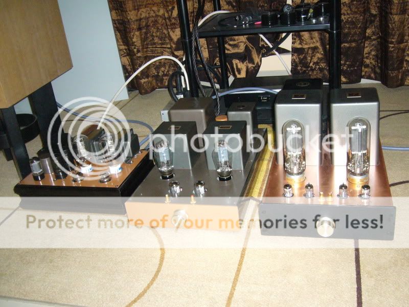
Thanks Commtech, Your system look very perfect. I like it.
btw, just to let you understand my grounding can cause problem or not.
I have 2 star ground point. 1 for left & 1 for right. Driver stage & power stage ground connected to their own Left / Right star ground.
Then this 2 star ground go separate wire to p/s ground.
btw, just to let you understand my grounding can cause problem or not.
I have 2 star ground point. 1 for left & 1 for right. Driver stage & power stage ground connected to their own Left / Right star ground.
Then this 2 star ground go separate wire to p/s ground.
Thanks Commtech, Your system look very perfect. I like it.
btw, just to let you understand my grounding can cause problem or not.
I have 2 star ground point. 1 for left & 1 for right. Driver stage & power stage ground connected to their own Left / Right star ground.
Then this 2 star ground go separate wire to p/s ground.
i doubt so. i have a hunch u have connected the C3M incorrectly.
Yamamoto A-09S schematic.
An externally hosted image should be here but it was not working when we last tested it.
Hi, Wavebourn.
Yes , I did measured 3.1v @ cathode & 95v @ screen grid. I slightly changed the zener value to increase the screen voltage. & this been successfully tested on my friend system.
So if you increased voltage on screen grid you need to increase as well resistance in cathode. If B+ is 385V, you have 10V on anode, that means current is 375/110 mA. The tube is probably saturated.
I'm building a clone too. One thing I have noticed is that the resistor values are very different in the production a09s compared to the ones in the schematic.
Maybe a stupid question, but are you using 20volt heater on the c3m ?
Yes, C3m filament is 20V!
3.1V on the 1K cathode resistor = 3.1mA current.
C3m unhappy with this low current, 16-30mA is optimal.
C3m datasheet:
if tube saturated (?) - 10V anode-cathode - anode current apx. 10mA, independently of the grid (G1) voltage.
I think this tube have misconnected pins.
16-30mA? that would be optimal in triode mode.
i am also suspecting wrong connections, especially the pin orientations.
but only if there is a picture, then we can tell.
Last edited:
- Status
- This old topic is closed. If you want to reopen this topic, contact a moderator using the "Report Post" button.
- Home
- Amplifiers
- Tubes / Valves
- Yamamoto 09S 300B SE Amp Problem