
There is mentioned at the schematic you attached as follows:
"(C)/ Tricomp 2011 Free for all non-commercial use"
What do you want to say with this ?
The circuit you attached has been invented some 60 years ago.
So has every other tube-circuit you see on the forum. I just don't want commercial exploitation of this complete amp., that I built. The 6AN8 pre-amp/phase-inverter is of course only half of the amp. The rest may easily be found if you search Google with '2C34'.
Yes, I know I haven't the faintest hope of preventing someone determined on exploiting not doing so....
I really don't want you opinion on the copyright but I would love your opinion on the circuit. It's very different from the regular phase-inverter and I haven't seen it used anywhere before in recent times. In my opinion it outperforms the split-load P/I's I've been working with/building.
rgds,
/tri-comp
So has every other tube-circuit you see on the forum.........
I really don't want you opinion on the copyright but I would love your opinion on the circuit. It's very different from the regular phase-inverter and I haven't seen it used anywhere before in recent times. In my opinion it outperforms the split-load P/I's I've been working with/building.
rgds,
/tri-comp
No, every other circuits here do not have similar "copyright-marking" you used.
The circuit you have "invented" again can be found from Wireless World August, 1947. The article concerning this is: " Push-Pull Phase-Splitter New High-Gain Circuit" by E. Jeffery.
http://livinginthepast-audioweb.co.uk/index.php?p=higainsplitter
The same circuit is later published at "Amplifiers, the why and how of good amplification" by G. A. Briggs, 1st edition March 1952, at the page 101 (A high gain phase splitter circuit)
And if I do not remeber badly wrong the circuit is also presented at the "Radiotron Designer's Handbook 4th edition" by F. Langford-Smith, 1953.
And you wanted my opinion about the circuit: it has very bad frequency response and far too high gain for any practical application.
Last edited:
You really do go a far way to hang someone out!
What I meant was that all other tubecircuits on the forum has been invented 60 years ago, not the thing about copy-rights!
Of course if you're set to pick a fight there's always a way...
I never took credit for inventing the circuit; I just modified it to suit my taste. Something everyone does, actually HAVE to do, ref. the 60 years above. I don't know if that's enough to claim a copy-right and I don't care. The (c) was just put there to deter commercial use, not to pick a fight.
If the circuit has a bad frequency response is just a matter of testing it, as I have built it already. Since I have a Scope and a LF-generator (ISO-TECH 6022 & TTi TG2000) I'll do just that. You may even be right and I have a chance to improve it. Not that listening to it suggest it's necessary.
As for amplification I can say it fits extremely well with a pair of 5687-CF driven 2C34 in AB2-PP with NFB.
Anyway, I think this subject should be taken to another thread as it's straying somewhat from the initial subject.
However, it may be interesting for Kagliostro and others to know precisely how well it performs regarding frequency response with and without NFB.
Too late today; I'll get back with measuring-results tomorrow.
rgds,
/tri-comp
Last edited:
Anyway, I think this subject should be taken to another thread as it's straying somewhat from the initial subject
No, don't worry all is fine as is
K
This boot-strapped version is not so well known but I highly recommend it ...
/tri-comp
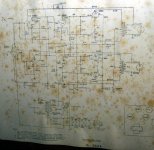
Below is the simulated plot of the frequency response of your circuit.
An externally hosted image should be here but it was not working when we last tested it.
As you see the gain is not as high as it shoud. Also the frequency response and the AC-balance at low frequencies is poor. The low gain is due to some 35 V andode voltage. Instead it should be above 100 V.
Next plot is after I modified your circuit:
An externally hosted image should be here but it was not working when we last tested it.
And here is the modified schematic: (free for all purposes including commercial use)
An externally hosted image should be here but it was not working when we last tested it.
I didn't measure exact output and frequency response of this amplifier before, as it was built more than a year ago and the test-equipment I have now was acquired only a few months ago.
The amp is installed and in use every day and sounds extremely well on my B&W 685 speakers:
Freq. resp.: 49Hz ~ 50KHz, -6dB
Spl.: 88dB (2.83V/1m)
These are the measured data of the whole amp. on an 8R dummy-load.
First w/o NFB, 1Vpp Sinus input.
Volumepot. adjusted to 1Watt output (8Vpp/8R) at ref. 1KHz (Setting approx. 10o'Clock)
Flat Midrange response from 600Hz to 6KHz. (8Vpp)
Bass response from 600Hz even drop till 70Hz -6dB (4Vpp)
Sub-Bass response from 70Hz even drop till 20Hz -12dB (2Vpp)
From 6KHz even drop till 23KHz -6dB (4Vpp)
Now with NFB applied, 1Vpp Sinus input.
Volumepot. adjusted to 1Watt output (8Vpp/8R) at ref. 1KHz (Setting approx. 1o'Clock)
Flat Response from 80Hz to 24KHz (8Vpp)
Sub-Bass response from 80Hz to 40Hz very small, even drop (maybe -1~2dB) then accellerating even to -6dB at 10Hz (4Vpp)
Subsonic response from 24KHz to 38KHz flat except slowly peaking at 30KHz (+3dB).
Beyond 38KHz even drop till 57KHz -6dB (4Vpp)
About Gain/Sensitivity:
It is absolutely perfect with NFB applied. Volume at full throttle requires an input of 0,5Vpp for max. output at 1KHz.
About Frequency Response:
Please say where the data looks bad, because I can't really spot the problem.
rgds,
/tri-comp
Last edited:
When a good desing methods are used, then every part of the whole circuit should perform well and their performance should be optimized separately.
Not so that the bad frequency response of the voltage amp./phase splitter will be fixed with GNFB. You can see from your own circuit diagram that the bias of the 6AN8 pentode is badly wrong. The anode voltage is only 35 V, which is far too low. (pls. calculate).
Then the simulation shows that the outputs are unbalanced badly at bass frequencies. Why that should be tolerated when it can be perfectly balanced ? This causes not only the drop at frequency response, but also severe distortion at bass end.
The reason why the sensitivity/gain is now perfect is that your circuit do not perform as planned. It's gain is only some 40 dB but it should be above 60 dB if the circuit worked as planned. In such case the sensitivity would be far different.
OK, thanks for taking an interest.
I'll try your suggestions in time but now I'm a bit stressed with work.
It will be interesting to measure and listen to the outcome.
The Phase-inverter output can swing around 80Vpp g-to-g which of course if far above what's required here.
rgds,
/tri-comp
I'll try your suggestions in time but now I'm a bit stressed with work.
It will be interesting to measure and listen to the outcome.
The Phase-inverter output can swing around 80Vpp g-to-g which of course if far above what's required here.
rgds,
/tri-comp
This Jeffery cathodyne is very complicated circuit and it's performance depends much about the indvidual tube and it's characteristics.
Actually it should be fine tuned for each (L+R) channel.
I really do not see the reason for such high gain and the complications this may cause.
An ordinary pentode driven cathodyne gives 46...50 dB gain which is just fine for most of the output tubes (in UL and pentode mode). There is still up to 20 dB spare gain for sufficient GNFB.
I have design and built a commercially manufactured PP amp with such pentode-cathodyne with soviet 6F12P and it works fine.
An externally hosted image should be here but it was not working when we last tested it.
This is the cathodyne circuit I have used:
I prefer not to DC-couple voltage amplifier and phase splitter.
Both has optimum operating point which usually are not the same.
An externally hosted image should be here but it was not working when we last tested it.
I prefer not to DC-couple voltage amplifier and phase splitter.
Both has optimum operating point which usually are not the same.
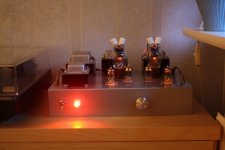
The real reason why I didn't use the tested and proven circuit like yours is that I would like to experiment and do things way off the ordinary. And that's only because not a lot of people did it before, not because 'ordinary' isn't good or even good enough. To me the challenge is to have something out of the ordinary function well, for what it wasn't originally intended. To my knowledge no-one did the output-section related to the above posted pre/inv-section. It's a 2C34 Push-Pull Class AB2 Cathode-Follower-driven stage with VVT-transformers. It sounds extremely well and it may even improve with your suggested modifications. I would post the schematic but unfortunitely it's also marked with copyrights ") The picture attached of the amp is mine and therefore no question about (c).
The picture attached of the amp is mine and therefore no question about (c).
I agree with you calculations of Va ~ 40V of the input-pentode. I arrive at the same conclusion as Ik is close to 1mA. However, measuring the actual voltage with a DVM with an input-R of 10Mohm shows Va ~ 125V. Now, that can't be true, but the scope confirms it and reveals no self-ocsillation that might cause distorted readings. Any explanation?
One question: C6 you propose to be 10uF. I have read somewhere that this cap. shouldn't be increased too much as it may result in a kind of low-frequency self-oscillation; a sort of motorboating perhaps. What's your view on this?
You did a VERY beautifull amplifier and I have no questions about it performing well if you say it does.
rgds,
/tri-comp
The picture attached of the amp is mine and therefore no question about (c). I agree with you calculations of Va ~ 40V of the input-pentode. I arrive at the same conclusion as Ik is close to 1mA. However, measuring the actual voltage with a DVM with an input-R of 10Mohm shows Va ~ 125V. Now, that can't be true, but the scope confirms it and reveals no self-ocsillation that might cause distorted readings. Any explanation?
One question: C6 you propose to be 10uF. I have read somewhere that this cap. shouldn't be increased too much as it may result in a kind of low-frequency self-oscillation; a sort of motorboating perhaps. What's your view on this?
You did a VERY beautifull amplifier and I have no questions about it performing well if you say it does.
rgds,
/tri-comp
Attachments
Last edited:
C6 is the boot-strap "pump" capacitor. As you see it is 100 nF at your schematic and the impedance/resistance which it supplies is some 35 kohms (250k paralell with 40 k). This makes the -3 dB corner frequency about 45 Hz. This in turn means that the impedance of the cathodyne's cathode section begins to increase below some 100 Hz and starts to approach the 40 k cathode resistor, while it should be 20kohms. At the same time the impedance at the anode remains 20k and is not depending on the frequency. Therefore the two outputs get badly unbalanced below 100 Hz. In my simulation C6 was 10 uF but I checked it again with 1 uF and this is sufficient value. The balance is good down to 15 Hz. The possible unstability (motorboating) is depending on many other thing too, mostly how big GNFB is used. You have done a real good looking amplifier.
- Status
- This old topic is closed. If you want to reopen this topic, contact a moderator using the "Report Post" button.
- Home
- Amplifiers
- Tubes / Valves
- I'm looking for 6an8 (as V1) schematics