I finally received all my transformers from James in Taiwan. They were a pleasure to deal with.
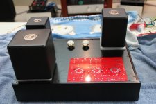
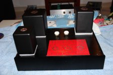
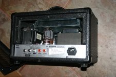
My chassis has holes cut in the back for IE and binding posts. I rotated the back piece so I can have the amps sit as a mirror image to each other.
I'm looking at two possibilities now. But I am open to suggestions and advice. The one I like the most is with the Power transformer in the front with the leakage from front to back and the choke behind it in the corner. I was going to point it the same way. The output transformer is on the right side with the leakage pointing towards the output tubes. On the Uniamp board the heaters are along the front of the PCB against the front wall.
The other option I was thinking of was the Choke in the front and PT in the rear with the same orientation.
I'm waiting for the vent plates I ordered for the KT88's I'm ready to start making holes. Any advice you might provide is appreciated.
Attachments
You don't show a ruler, but one can get some idea on chassis and transformer size by the "valve holder" pinout.
The problem with encapsulated transformers is knowing which quatrant the internal iron and the core lay. Rule: Keep the mains transformer & choke proximity furthest away from the inputs, as the choke has a gapped core and will radiate a smoothing hum field.
Is it a Steel chassis ?
richy
The problem with encapsulated transformers is knowing which quatrant the internal iron and the core lay. Rule: Keep the mains transformer & choke proximity furthest away from the inputs, as the choke has a gapped core and will radiate a smoothing hum field.
Is it a Steel chassis ?
richy
The chassis are aluminum. The inner dimensions are 400mm long, 295 deep and 75mm tall or 15.75" by 11.6 by 3". The iron is as follows:
6255H F OT 106mm by 80mm
9610 PT 122mm by 122mm
10-200S ch 90mm by 65mm
I can tell the orientation of the PT and OT from the drawings on the website °í·s¹q¤l¤u·~ªÑ¥÷¦³¤½¥q
I need to write and verify the chokes orientation inside box. Thanks for your response Richy
6255H F OT 106mm by 80mm
9610 PT 122mm by 122mm
10-200S ch 90mm by 65mm
I can tell the orientation of the PT and OT from the drawings on the website °í·s¹q¤l¤u·~ªÑ¥÷¦³¤½¥q
I need to write and verify the chokes orientation inside box. Thanks for your response Richy
The chassis are aluminum. The inner dimensions are 400mm long, 295 deep and 75mm tall or 15.75" by 11.6 by 3". The iron is as follows:
6255H F OT 106mm by 80mm
9610 PT 122mm by 122mm
10-200S ch 90mm by 65mm
I can tell the orientation of the PT and OT from the drawings on the website °í·s¹q¤l¤u·~ªÑ¥÷¦³**¤½¥q
I need to write and verify the chokes orientation inside box. Thanks for your response Richy
Sorry, but the choke is a PSU filter choke?
I would separate the PSU from the audio paret as much as possible.
As you need access to the back plate for signal input, signal output and ac supply, I would separate using one side for PSU and the other for the amp.
The PSU trandformer would be near the back to avoid having 230V AC running inside the case.
As you need to transport the signal input to the front (do you? for volume control?) I would also place the output tr on the back so that the wires will solder directly to the binding posts.
This would be my aproach but only placing all on top of the box you get the notion if it will work OK, also estetically
When I make monoblocks I use the back for PSU and the front for the amp, but use input and output on the sides, front part of the box.
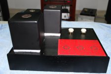
Your draft looks like my option 2 in the first post except for the output tubes. I have them to the left of the transformer. The OT and board are 240mm together. My board is 295 deep and my vent plates I'm putting on are 65mm. I couldn't put the vent plates on if I put the output tubes in front of the OT.
Last edited:
Your draft looks like my option 2 in the first post except for the output tubes. I have them to the left of the transformer. The OT and board are 240mm together. My board is 295 deep and my vent plates I'm putting on are 65mm. I couldn't put the vent plates on if I put the output tubes in front of the OT.
From the picture it looked as if you could just squeese that on! even if in some part the PCB will get bellow the power tubes.
If not, tried to place one power tube each side of the output tr?
Nice box, Can I buy one similar?
I should have the plates for the output tubes early next week. I may be able to slide the tube plates over the PCB? I take a look when they get here.
As far as the box goes. I'm working in China and I found the seller on the Chinese ebay/taobao. I would be happy to send you the link. They have it in silver and black. I paid $65 each here in China. I thought that was a bit high but it fit my needs. If your really interested I could inquire about shipping. I can speak the language ok but I can't read or write.
As far as the box goes. I'm working in China and I found the seller on the Chinese ebay/taobao. I would be happy to send you the link. They have it in silver and black. I paid $65 each here in China. I thought that was a bit high but it fit my needs. If your really interested I could inquire about shipping. I can speak the language ok but I can't read or write.
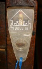
4 in 1 tool
Most of my work is from DIYer's guitars and amps with issues from pickup/xfrmr polarity issues. Here is one of my builds, that defies explanation.
Will spill the beans with this simple tool. Power the amp up and czech the +/- of the xfrmrs.
Most of my work is from DIYer's guitars and amps with issues from pickup/xfrmr polarity issues. Here is one of my builds, that defies explanation.
Will spill the beans with this simple tool. Power the amp up and czech the +/- of the xfrmrs.
Attachments
Last edited:
Hi,
I do NOT like the On-Off switch brought forward to the front, and in proximity of a Selector Switch. Avoid this !!
I like the Power Transformer tucked away in the left rear corner, as you drew it. Can you somehow locate the On-Off switch back there too?
I do NOT like the RCA input jacks in the rear vertical portion of the amp, requiring LONG wires to reach the selector and volume switches. TOO much chance for a degrade, of lowest level signals, in those long wire runs !!
I would have RCA jacks on the TOP of the amp chassis, right front corner or front middle area, so you can insert interconnects into the amp from any direction, and KEEP the lead length 2 inches or less, into the amp.
The choke, away from the power transformer is good, but do NOT let it crowd the Selector Switch, especially if its choke input, as the first filter element
Then, you have it !!
Jeff
Bad idea, IMHO. It guarantees that the two channels cannot be identical (e.g. stray capacitance), as you can't get mirror image valves. It may look nice, but the main purpose of an audio amplifier is not to look nice but to amplify.nanchangbob said:My chassis has holes cut in the back for IE and binding posts. I rotated the back piece so I can have the amps sit as a mirror image to each other.
Member
Joined 2009
Paid Member
but the main purpose of an audio amplifier is not to look nice
where on earth did you get that piece of misinformation ?
")
but the main purpose of an audio amplifier is not to look nice but to amplify.
One wouldn't get away with that one when my wife has control over the looks in the living room. A tube amp has to look nice as well with the speakers to blend in. My 1950's emperors closet is a retreat with equipment and wires hewed around is for my eyes only !
rich
One wouldn't get away with that one when my wife has control over the looks in the living room. A tube amp has to look nice as well with the speakers to blend in. My 1950's emperors closet is a retreat with equipment and wires hewed around is for my eyes only !
rich
Hi Richard,
Trust you and Anna are well. Send me a PM if you get time.
Regards,
Karl (and Diane)
- Status
- This old topic is closed. If you want to reopen this topic, contact a moderator using the "Report Post" button.
- Home
- Amplifiers
- Tubes / Valves
- Transformer orientation and suggestions.