I assembled this amplifier, its very good but quite hard to stabilize.
Having debugged it, I would suggest to do the following:
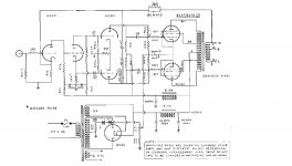
1) Install separate BIAS pots.
2) Install 10 Ohm cathode resistors in order to measure idle current.
3) Lift fake center tap of filament winding (2 x 100 Ohm resistors) to about 30V.
4) Install trim pot instead of fixed NFB resistor.
I've got over 60W with pair of 6550/KT88/KT120 (tested all 3 types of tubes), THD at 1KHz was something 0.15% - 0.25% for power up to 50W.
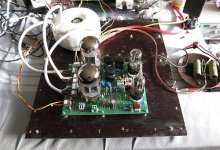
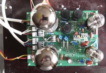
Pictures of breadboard PCB build attached.
Having debugged it, I would suggest to do the following:
1) Install separate BIAS pots.
2) Install 10 Ohm cathode resistors in order to measure idle current.
3) Lift fake center tap of filament winding (2 x 100 Ohm resistors) to about 30V.
4) Install trim pot instead of fixed NFB resistor.
I've got over 60W with pair of 6550/KT88/KT120 (tested all 3 types of tubes), THD at 1KHz was something 0.15% - 0.25% for power up to 50W.
Pictures of breadboard PCB build attached.
Attachments
- Status
- This old topic is closed. If you want to reopen this topic, contact a moderator using the "Report Post" button.