Hi,
I got the point with the lower cathode resistor. Could you link the datasheet you used?
What I don't understand properly: I thougt, the drive resistor is determined by the wanted drive to the upper valve. Im my opinion, the 10K brings only 25% of drive, so modulation of the upper valve is poor. Or does the higher current improve the amplification factor of the valve, so that only 10 is needed??? Or does the voltage drop becomes unacceptable now with 47K?
I always thought, the SRPP hast to low drive to the upper valve, because the cathode resistor is only determined by bias requirements, and upper valve modulation is a happy sideffect...
I always thought, u-follower is more perfect push-pull then SRPP... And betafollower would be constant current anode load alike.... MHMMMM...
The data I used was on a sheet of paper in a book, but I'm sure google can find a 12AX7/ECC83 datasheet for you or an RCA receiving valve handbook.
Raising the 'drive resistor' reduces the output impedance from the upper cathode. It raises the effective anode impedance of the active load - roughly mu times the resistor. As the ECC83 is happier with higher anode voltage we want to drop as little as possible. 10k gives us a 1M effective load for the lower valve. You could try going a little higher but there is a balance to be struck. The upper valve already has the same drive as the lower valve just from having the same cathode resistor.
Mu-follower is not push-pull hardly at all. It is really a hybrid of active load and bootstrapped cathode follower. Only the SRPP is balanced, and only that when properly designed. There is a reasonable write-up on Merlin Blencowe's site: ValveWizard. The upper valve modulation in the SRPP is not 'a happy side effect' but the whole point of the circuit.
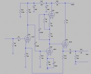
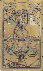
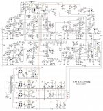
This is the circuit I built on the eBay board that I purchased a few years ago. The 6DT8 is basically a 12AT7 without a center tapped filament. I did test this circuit as I built it and I feel the front end is biased in a more linear operating point than the original circuit that used a 12AU7 (in the directions and schematic that came with the board). I used a lower closed loop gain as well. I'm not using this preamp currently but it functioned fine for me.
Attachments
Hi there.
I took a look at the characteristics of the 12AX7 as published by GE in December of 1961. These characteristics curves show that at 1mA plate current the mu of the 12AX7 is just about 100, essentially independent of operating conditions. When a device behaves that linearly, essentially no significant change in mu over a range of anode currents, the tube has to be the "cat's meow" as far as amplifier linearity is concerned.
In other words, if you operate the 12AX7 as a resistance coupled voltage amplifier with a 210V power supply rail the near optimal operating point should be with a 70k resistor in the plate-lead, (essentially equal to 68k) and the bias of the 12Ax7 should be adjusted to 140V across the tube and 70V across the plate resistor, a little more than 1mA in the plate-circuit.
Vacuum tubes are, in general, so well behaved and so linear, that it is nearly impossible to cobble together a circuit using a 12AX7, that has poor harmonic performance.
Greetings: Hans J Weedon
But this sets the idle current, the additional resistor modulates the current to a wished symmetry upper/lower valve... So my unerstanding of SRPP is such:The upper valve already has the same drive as the lower valve just from having the same cathode resistor.
Lower valve cathode resistor is "local feedback", upper valve cathode resistor derives a drive signal.
u-Follower:The additional resisor ca be used to "replace" the drive from the upper cathode resistor with a correct sized drive, so that upper an lower valve are driven in a symmetric manner. I the current set is couple with 1M, so drive is only done with the additional resistor of the u-Follower...
(My explanation is no load condition-what is the case in the CAT1, because a cathodefollower added...
So, getting to the point Hans showd: Looking at the u-curves of the added datasheet, it seems that 3mA could be a stable u Area.
Hans said, 1mA gives a stable u... I can't see this. Please explain...
To get the benefit of constant mu the valve has to see a high (ideally, infinite) anode load. This is because the transconductance (and hence anode impedance) are strong functions of current. 70k is far too small a load for an ECC83. You need at least 10 times the anode impedance, if possible. For that you need either a very high supply rail voltage and a high value resistor, or an active load.HJWeedon said:I took a look at the characteristics of the 12AX7 as published by GE in December of 1961. These characteristics curves show that at 1mA plate current the mu of the 12AX7 is just about 100, essentially independent of operating conditions. When a device behaves that linearly, essentially no significant change in mu over a range of anode currents, the tube has to be the "cat's meow" as far as amplifier linearity is concerned.
In other words, if you operate the 12AX7 as a resistance coupled voltage amplifier with a 210V power supply rail the near optimal operating point should be with a 70k resistor in the plate-lead, (essentially equal to 68k) and the bias of the 12Ax7 should be adjusted to 140V across the tube and 70V across the plate resistor, a little more than 1mA in the plate-circuit.
In a mu-follower the extra resistor adds to the drive from the upper cathode resistor, not replace it. In most cases this means the balance is lost, so we now rely on the linearity of the valve. That is why SRPP is best for non-linear valves, but mu-follower is best for linear valves.HVfanatic said:u-Follower:The additional resisor ca be used to "replace" the drive from the upper cathode resistor with a correct sized drive, so that upper an lower valve are driven in a symmetric manner.
Running an ECC83 at 3mA with low anode voltage means that the grid voltage is low and inside the grid current region. This adds distortion by loading the previous stage. ECC83 is a wonderful valve when used in the right circuit, but behaves badly in the wrong circuit. This may be why it is so unpopular with some people.
Last edited:
Hi guys.
I may have been wrong in my understanding about the operation of the 12AX7 and optimal plate-current. The enclosed GE<PDF> data-sheet shows that the recommended load resistor in the recommended operating region is between 100k and 510k.
But I do agree that 3mA is not good that is in the forward biased region of Grid#1. Looking at the curves for mu, though on page 4 I may have been mislead.
Hans J Weedon.
Attachments
3k is fine if that is the best that can be achieved: high anode resistor from a lowish supply rail. Given an active load we can do better by using a bit more current, so smaller Rk. Ideally approaching 1mA as that is where the mu curve becomes flat. The fact that the wrong value for the upper grid resistor gives less distortion (in a simulation?) suggests that the valves are running non-linear, which means the wrong bias point is being used.
Hello from Salem MA.
There are at least one thing wrong with using a vacuum tube as a load in an amplifier.
My number one objection is that unlike transistors, indirectly heated vacuum tubes normally have a heater and a cathode. I know that the manufacturers spec is that there can be a significant voltage differential between the heater-coil and the cathode tube.
The way the cathode is constructed is: A small cylinder of nickel has a folded thin wire of usually tungsten inside. This tungsten wire has an insulating coating so that there effectively is an insulating barrier between the heater and the cathode.
This heater / cathode barrier represented a significant technological challenge in production. I learned from my Dad, who was an expert at these things that for a reliable design you do not apply more than a few volts between the cathode and the heater.
There is no realistic way of preventing a noisy current to flow between the actual cathode and the heater wire. If this voltage is much more than about 20V there will be a current flowing between the heater and the cathode terminal.
I know that in indirectly heated rectifiers the heater to cathode voltage is permitted to be as large as 450V DC. that is OK for a rectifier tube, because the power-supply is normally bypassed well.
In an application where we can expect relatively low signal voltages the unintended current between cathode and filament may become a major source of noise and signal.
I therefore firmly believe that using a tube as a load in a high quality preamp is counter-indicated as my patent lawyer would say.
Specifically, if the heater DC voltage is negative with respect to the cathode, the heater wire will emit electrons that lands on the cathode, this is going to be a noisy current because the heater is not designed to be an emitter, it just is.
Conversely, if the heater is more positive than the cathode, the heater will become the anode and again a noisy current flows.
This heater / cathode current-flow is not something new, but may resurface again because of lost knowledge. In other words: keep the differential; voltage between the heater and cathode as low a possible, and worry about the noise later.
Resistor load: no problem, tube load will become noisy with time.
Hans J Weedon.
All the people who have looked into this seem to agree that lowest noise and longest valve life are given by making the heater positive, not zero as you suggest. The optimum appears to be about +40V, but it is a broad curve so the exact value is not too important. It does not act as an anode with respect to the cathode because the active cathode surface does not face the heater.
Active loads and cathode followers have been used without problems for a long time. At the output of an active load the signal has received significant amplification so noise will not be a huge issue anyway.
One proviso: it is said (by some) that NOS valves may have better heater-cathode insulation than modern valves.
Hi there.
Thinking back many years, I may very well be wrong in claiming the there should be no DC voltage between the Cathode and the Filament in a vacuum tube amplifier. Sorry about that. I remember back to the 4+1 Audio amplifier published by Phillips and Mullard in the 1950s. It used an EF86 pentode input amplifier and an ECC83 as phase inverter, driving a pair of EL86s in push pull.
Since the phase inverter was a long tailed pair the cathodes were biased up some 35V and the recommended DC bias for the heater centertap was indeed 40V. Under those bias conditions the filament in the indirectly heated cathode was always biased positive with respect to the nickel tube used as a cathode. My guess is that since the heater was hotter than the nickel cathode, no noisy emission current could flow from the heater to the cathode, and the cooler nickel cathode did not emit enough current to worry about.
I stand corrected. Thank you very much. When I am wrong, I am wrong.
Hans J Weedon
Salem MA.

")
- Home
- Amplifiers
- Tubes / Valves
- DIY CAT SL1 preamp