Υes , it has to do only with the miller capacitance of the 12AX7 but the raise of the rpWRT to the 150pF cathode cap I believe this was intended to compensate for the considerable miller capacitance of the 12AX7. Cathode current feedback [large cathode resistor] in a mu-follower has no effect on gain, but it does raise rp significantly which in conjunction with miller capacitance does result in really poor HF response. (The effective rp in this circuit is not constant, decreasing slightly with frequency due to that cap.)
and the outuput impedance of this stage will not affect the HF gain because the next stage is a DC cathode follower with very high input impedance .
Last edited:
Kevinkr:
Thanks for shedding some light on this circuit. As the 150pF only has an effect from around 1MHz it is clearly there to aid stability. The centre stage is not a mu-follower, but an active load, even with a 1M grid resistor (unless the signal take-off from this is also wrong in the circuit diagram).
Thanks for shedding some light on this circuit. As the 150pF only has an effect from around 1MHz it is clearly there to aid stability. The centre stage is not a mu-follower, but an active load, even with a 1M grid resistor (unless the signal take-off from this is also wrong in the circuit diagram).
Kevinkr:
Thanks for shedding some light on this circuit. As the 150pF only has an effect from around 1MHz it is clearly there to aid stability. The centre stage is not a mu-follower, but an active load, even with a 1M grid resistor (unless the signal take-off from this is also wrong in the circuit diagram).
No it's not utilized as a mu-follower but as a common cathode with active load, but it's convenient to (incorrectly) call it such.
 The signal was indeed tapped off of the lower plate in the one I worked on.
The 150pF IMO compensates for HF phase shift introduced by the combination of very high rp due to the cathode feedback and the miller capacitance of that stage. I don't know whether or not it would oscillate without it, but I suspect that might be the case with the very capacitive interconnect cables popular at the time. (And which frankly still are)
There were a few revisions of this very long lived design over time - most I believe to be very subtle, but I have not seen one in decades.
Interesting that so many of the diagrams were wrong. Is it everyone copying a poor reverse-engineered one, or a deliberate spoiler? In either case it is a warning: several diagrams all agreeing doesn't mean they are right. Did nobody ask any questions?
The use of the 150pF to give some phase advance in the forward path is unusual. I don't think I have seen that before.
The use of the 150pF to give some phase advance in the forward path is unusual. I don't think I have seen that before.
Interesting that so many of the diagrams were wrong. Is it everyone copying a poor reverse-engineered one, or a deliberate spoiler? In either case it is a warning: several diagrams all agreeing doesn't mean they are right. Did nobody ask any questions?
The use of the 150pF to give some phase advance in the forward path is unusual. I don't think I have seen that before.
I'm pretty sure the misinformation is deliberate and intended to foil slavish copying of the design. Anyone who understands good tube design will figure this out quickly and fix the obvious spoilers.
During the original time frame this was designed companies like VTL, ARC (SP-3/6), and MFA were making "improved" versions of what was essentially the Marantz 7 topology. This represented a significant improvement in performance IMO over those designs. And NO I would not build anything inspired by a design based on any of these today.
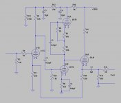
I bought one of the blank circuit boards on ebay a few years ago. This is the circuit that I used on it. It worked well and sounds fine, but I agree it is very complicated.
I really didn't think the original circuit was biased optimally, so I made several changes. I used the 6DT8 since they are similar to the 12AT7 but very avaialble and very inexpensive. I didn't need all the gain of the 12AX7.
The board required a trace to be cut or you'll but too much voltage on the heater-cathode. I used two heater supplies and boosted the top tube heaters.
I'd really only recommend this board if you want to experiment with the mu follower in a feedback loop.
Attachments
I bought one of the blank circuit boards on ebay a few years ago. This is the circuit that I used on it. It worked well and sounds fine, but I agree it is very complicated.
I really didn't think the original circuit was biased optimally, so I made several changes. I used the 6DT8 since they are similar to the 12AT7 but very avaialble and very inexpensive. I didn't need all the gain of the 12AX7.
The board required a trace to be cut or you'll but too much voltage on the heater-cathode. I used two heater supplies and boosted the top tube heaters.
I'd really only recommend this board if you want to experiment with the mu follower in a feedback loop.
Interesting. What is the different in terms of sound performance after those the changed that you made...
Have you ever try to maintain the ecc82 input drive?
Should I change the value of the components if I used the 12at7 instead of the 6dt8?
You can use a 12AT7 directly, just make sure you have the heater wired correctly.
I don't understand what you mean by "Have you ever try to maintain the ecc82 input drive?"
I originally tried 1M at R6, I don't remember why I went to the lower value. The board showed 1K there but I made lots of changes to it. I'll see if I can find my notes.
I don't understand what you mean by "Have you ever try to maintain the ecc82 input drive?"
I originally tried 1M at R6, I don't remember why I went to the lower value. The board showed 1K there but I made lots of changes to it. I'll see if I can find my notes.
Have you ever tried to remove C4 820pF and listen to the preamp or measure it's frequency response to see the differences with and without the C4 capacitor .I bought one of the blank circuit boards on ebay a few years ago. This is the circuit that I used on it. It worked well and sounds fine, but I agree it is very complicated.
I really didn't think the original circuit was biased optimally, so I made several changes. I used the 6DT8 since they are similar to the 12AT7 but very avaialble and very inexpensive. I didn't need all the gain of the 12AX7.
The board required a trace to be cut or you'll but too much voltage on the heater-cathode. I used two heater supplies and boosted the top tube heaters.
I'd really only recommend this board if you want to experiment with the mu follower in a feedback loop.
You can use a 12AT7 directly, just make sure you have the heater wired correctly.
I don't understand what you mean by "Have you ever try to maintain the ecc82 input drive?"
I originally tried 1M at R6, I don't remember why I went to the lower value. The board showed 1K there but I made lots of changes to it. I'll see if I can find my notes.
HI,
the original circuit board design have the 12AU7 (ECC82) as the input stage while I saw it has been changed to 6CG7 on your schematic.
Anytime you do a direct coupled feedback the bias point of the input tube is critical. I chose the 6CG7 since it had a greater grid-cathode voltage at my operating point than the 12AU7 did and that allowed me to set the closed loop gain where I wanted it to operate. The voltage swing from the 6CG7 is minimal, but I have found it ot be a very linear tube if biased properly.
I never had any problem of instability or overshoot and ringing in any stage with completely unbypassed cathode resistor , IMΗO the problem is somewhere else and you can fix it with other ways , it depends on the experience of each one ( this is not a hint to anyone ) Thanks .Yes, if you remove the 820pF capacitor their is significant overshoot and ringing. Their are other ways to compensate the circuit but adding that zero in the response takes care of instability and the capacitor is already available on the circuit board.
As I stated there are many ways to compensate this amplifier, the capacitor is one of them and there was already a place for it on the board. I altered the value to compensate the amplifier as I designed it.
When you put a mu-follower in a feedback loop you have to account for the open loop frequency response. The problem is you have three poles in the circuit and and they are too close together. Other possibilities are to alter C1 and R29 or C2 and R6 and their associated components. Be careful not to get too close to the roll off from R4 either. You could rebias the input stage as well.
You are correct, there are lots of possibilities and other ways to handle the required compensation.
Anytime you do a direct coupled feedback the bias point of the input tube is critical. I chose the 6CG7 since it had a greater grid-cathode voltage at my operating point than the 12AU7 did and that allowed me to set the closed loop gain where I wanted it to operate. The voltage swing from the 6CG7 is minimal, but I have found it ot be a very linear tube if biased properly.
So what is the bais voltage of the 6CG7 tube?
The problem is not in the stage, it is in the entire loop. The capacitor gives some phase advance so the loop is stabilised.Dimitris AR said:I never had any problem of instability or overshoot and ringing in any stage with completely unbypassed cathode resistor
Yes , it is true , yet I haven't any problem with such stage even if it is in an preamp consisting of two or three stages and with the use of NFB , I suspect the way that the NFB is placed in this preamp , and other cases like the layout of the PCBThe problem is not in the stage, it is in the entire loop. The capacitor gives some phase advance so the loop is stabilised.
.- Home
- Amplifiers
- Tubes / Valves
- DIY CAT SL1 preamp