Hello,
I'm just learning about tube amps and have come to a stumbling block on the issue of the cathode follower.
It's seems my head is stuck on the idea that in a vacuum tube, electrons flow from the negative cathode to the postive anode (plate) 'amplifing' the grid input, but when it comes to a cathode follower (increases current not voltage) it's seem that electrons are flowing from the plate to the cathode (I know this can't be right, is it?) and thus current is being drawn from the grid signal to the cathode.
I've read and I'm trying to understand this explaination from ampbooks.com but still not getting it...
"A basic triode amplifier is great for increasing the voltage of a signal. Its major problem is that it can't drive a very heavy load. Place a low-valued resistance across its output and it easily gets bogged down, which reduces the gain and makes it dependent upon the characteristics of the load. If the next stage is a voltage amp or a phase inverter, this isn't much of a problem. A tone stack, however, typically demands a lot of current from the driving stage, the amount of which depends on the signal characteristics and the tone control settings. A cathode follower mitigates this problem. It has no gain (in fact a slight loss), but it can easily drive the most demanding of tone stacks.
An increasing input signal voltage causes the plate current to increase, which increases the voltage across the cathode resistor, thereby making the cathode more positive with respect to ground. If the input increases the grid-to-ground voltage by 1 volt, then the increased plate current raises the cathode-to-ground voltage by almost 1 volt, leaving the grid-to-cathode voltage almost unchanged. The grid voltage increases but the cathode voltage "follows" it. Thus we get this circuit's name."
I know there must be some simple, laymen explination that I'm just not getting, if someone could enlighten me I would greatly appreciate it!
Cheers
John
Last edited:
You are thinking like a Physicist about electrons. The "correct" way to think about tubes is like an EE. THink about "holes" that cary positive carge flowing from plate to cathode. Engineeers don't give a hoot about electrons, current is always "positive".
The cathode follower is simple when you think about positive holes moving: Ohm's law causes a voltage across the load resister that depends on current. That voltage is the output signal. That's it.
The cathode follower is simple when you think about positive holes moving: Ohm's law causes a voltage across the load resister that depends on current. That voltage is the output signal. That's it.
There are no 'holes' in a valve. Don't think about electrons or holes, just think about AC signal currents and voltages. It's all about using the appropriate level of abstraction. You need electrons (and holes for semiconductors) to understand how an active device works internally, but you can then just treat it as a 'black box' in a circuit. Using appropriate levels of abstraction is really thinking like a physicist!
If a valve grid goes more positive then the cathode-anode current will increase. This will drop more voltage across any resistor in the cathode or anode circuits. If the resistor is in the cathode circuit then the change in voltage opposes the grid change, so it is an example of negative feedback.
If a valve grid goes more positive then the cathode-anode current will increase. This will drop more voltage across any resistor in the cathode or anode circuits. If the resistor is in the cathode circuit then the change in voltage opposes the grid change, so it is an example of negative feedback.
Another way to think of it is in term of impedances. The cathode follower is a buffer stage with very low output impedance. It protects your voltage gain stage from the signal distorting impedances of the external world. For example, you might increase the AC 'swing' with a comon cathode amplifer, but the cable, attenuator and input impedance of the next stage will ultimately distort that beautiful AC 'swing'. The cathode follower will protect (buffer) it.
Cathode follower.
Hi
Come on guys. please do not confuse a new-comer.
We can compare a cathode follower to the power steering that we all love in our cars. The grid of a cathode follower is like the steering wheel of a car with power steering, the cathode output is like the steering knuckle controlling the front wheels. The wheels do nothing unless the steering wheel is turned, similarly the cathode does nothing unless the grid tells it to.
There are bias levels in a tube that you have to contend with, that is done with capacitors that pass AC voltages, but leaves the DC bias voltages in place.
When properly done, the cathode follower can drive just about as much current into the load as it's standby bias current. in a typical tube that might be 100mA, not much drive for a speaker, but usually enough for a pair of headphones.
Just like the power steering, where the wheels do not do anything more than the steering wheel tells it to do, the output of a cathode follower does not do anything more than the grid input tells it to, but at significantly increased power level. If you have about 2V available for driving a pair of headphones, but not enough power behind it, put a cathode follower in between the signal; source and the load.
Hans J Weedon
 Unprotected email address removed by moderation to prevent spam.
Hi
Come on guys. please do not confuse a new-comer.
We can compare a cathode follower to the power steering that we all love in our cars. The grid of a cathode follower is like the steering wheel of a car with power steering, the cathode output is like the steering knuckle controlling the front wheels. The wheels do nothing unless the steering wheel is turned, similarly the cathode does nothing unless the grid tells it to.
There are bias levels in a tube that you have to contend with, that is done with capacitors that pass AC voltages, but leaves the DC bias voltages in place.
When properly done, the cathode follower can drive just about as much current into the load as it's standby bias current. in a typical tube that might be 100mA, not much drive for a speaker, but usually enough for a pair of headphones.
Just like the power steering, where the wheels do not do anything more than the steering wheel tells it to do, the output of a cathode follower does not do anything more than the grid input tells it to, but at significantly increased power level. If you have about 2V available for driving a pair of headphones, but not enough power behind it, put a cathode follower in between the signal; source and the load.
Hans J Weedon
Unprotected email address removed by moderation to prevent spam.'ve read and I'm trying to understand this explaination from ampbooks.com but still not getting it...
"A basic triode amplifier is great for increasing the voltage of a signal. Its major problem is that it can't drive a very heavy load. Place a low-valued resistance across its output and it easily gets bogged down, which reduces the gain and makes it dependent upon the characteristics of the load. If the next stage is a voltage amp or a phase inverter, this isn't much of a problem. A tone stack, however, typically demands a lot of current from the driving stage, the amount of which depends on the signal characteristics and the tone control settings. A cathode follower mitigates this problem. It has no gain (in fact a slight loss), but it can easily drive the most demanding of tone stacks.
An increasing input signal voltage causes the plate current to increase, which increases the voltage across the cathode resistor, thereby making the cathode more positive with respect to ground. If the input increases the grid-to-ground voltage by 1 volt, then the increased plate current raises the cathode-to-ground voltage by almost 1 volt, leaving the grid-to-cathode voltage almost unchanged. The grid voltage increases but the cathode voltage "follows" it. Thus we get this circuit's name."
I know there must be some simple, laymen explination that I'm just not getting, if someone could enlighten me I would greatly appreciate it!
Cheers
John
It's no wonder you're not "getting it": your source material is pure, absolute, unadulterated bull. The cathode follower is just another VT circuit that can not perform the magic of making a high voltage, low current, device into a high current, low voltage device. It's the same loadline regardless of whether the load's connected between the plate and DC rail, or whether it's connected between the cathode and DC ground. (Or whether it's split between the cathode and plate. It's always the same loadline.)
A stiff load pulls down the gain and linearity of a triode. However, the same applies to a cathode follower: it makes no difference where the load is connected. None. Absolutely none!. The cathode follower is a good device for presenting a Lo-Z source impedance, but only to a Hi-Z load (like the aforementioned tone stack).
The misapplication of cathode followers by running them into stiff, near vertical, loadlines is what's responsible for the negative reputation of the topology.
No. CF has much more negative feedback than a grounded cathode stage. It can't do magic, that is true, but for a given load a CF will drive it with less distortion until clipping begins. For a given load line a CF will provide about 1/mu as much distortion as the corresponding grounded cathode, as well as about 1/mu as much gain - exactly as the NFB equations predict.Miles Prower said:However, the same applies to a cathode follower: it makes no difference where the load is connected. None. Absolutely none!.
The source material quoted by the OP is woffly, but it is not as bad as you say.
Thank you all for your responses, I must admit though, I'm still at a loss. Mine you, I'm just learning basic electronics (Chapter 9 of 23 of our schools electronic course) but am burning to understand how guitar amps work.
If we could take a step back for one moment. I think what I'm having difficulty is understanding the actual guitar signal path. I know that in a triode amplifying stage a very small AC guitar signal enters the grid, this signal is 'amplified' by a stream of electrons flowing from the cathode to the plate (anode). This occurs because their is a positive potential at the plate with respect to the cathode, thus their is a one way current flow from cathode to plate. If the plate was made negative with respect to the cathode, electrons would be repealed and the current would stop.
So what is actually happening in a CF stage, between the Plate and the Grid, between the Grid and the Cathode and between the Plate and the Cathode with respect to voltages, current and actual guitar signal?
I've attached a diagram of a Fender 5F6-A Bassman's (normal channel only) that I've been using to try to get my head around this wall.
Thanks
John
Attachments
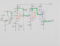
As the current pulses thru the plate resistor in stage 2 the voltage on the plate pulses from ohms law. You show 180v which would be the voltage with no signal. Let's say it goes up and down from 170v to 190v with signal applied. This is a 20volt peak-to-peak swing. That plate is connected to the 3rd stage's grid with the question mark. So the voltage on the "?" is also pulsing and therefore modulating/pulsing the current thru that 3rd stage. Swinging the voltage on a grid makes the current flowing from the cathode to the plate pulse up and down in unison.
That 3rd cathode resistor's current is therefore pulsing so the voltage on that cathode is pulsing, again due to ohm's law. The pulsing on that 3rd cathode is where the cathode follower's output is taken. The output is "following" the voltage on the cathode. The output of the 2nd stage is following the voltage on it's plate.
The diagram shows 180v on the plate of stage 2 (grid of stage 3) and 180v on the cathode of stage 3, which is not correct. The 3rd cathode would be a little higher in (DC) voltage than it's grid at idle. Perhaps 185-190 or so. The difference in voltage between a grid and its cathode (with no signal) is called "bias."
I know there must be some simple, laymen explination that I'm just not getting, if someone could enlighten me I would greatly appreciate it!
Let me try - step by step - in your terms:
Lets have a look at the 1st stage in your circuit V1a:
You are correct, there is a flow of electrons from the cathode to the plate.
This flow is influenced by the charge (amount of electrons) on the control grid.
Any change of the charge on the grid causes a change in the flow.
More electrons on the grid (more negative charge) reduces the current between cathode and plate.
Less electrons on the grid (less negative charge) increases the current between cathode and plate.
Hence the tube is in fact a voltage (grid) to current (plate/cathode) converter.
One of the main tube characteristics is therefore transconductance gm or S in the datasheets which is measured in mA/V.
That is milliamps (plate/cathode) per volt (grid).
So changes of grid voltage (input signal) are converted to changes of plate/cathode current.
The change of plate/cathode current in turn causes a change of voltage drop in the plate resistor (output signal).
Signal amplification happens when both gm and plate resistor values are big enough such that the change of the grid voltage causes a bigger change of the voltage drop in the plate resistor. And the cathode resistor is small enough such that there is no significant voltage drop across it.
Lets have a look at the 2nd stage in your circuit V2a:
Again, there is a flow of electrons from the cathode to the plate.
This flow is influenced by the charge (amount of electrons) on the control grid.
Any change of the charge on the grid causes a change in the flow.
Note, that the grid of V2a is connected to the plate of V1a by means of a capacitor.
This capacitor allows only changes in the plate voltage (AC) of the 1st tube to pass on to the grid of the 2nd tube, not the voltage (DC) itself.
Again, changes of grid voltage (input signal) are converted to changes of plate/cathode current.
The change of plate/cathode current in turn causes a change of voltage drop in the plate resistor (output signal).
Same as with V1a.
Finally lets have a look at the 3nd stage in your circuit V2b:
Again, there is a flow of electrons from the cathode to the plate.
This flow is influenced by the charge (amount of electrons) on the control grid.
But now, the control grid is directly connected to the plate of the previous stage, no capacitor is blocking DC.
And there is no plate resistor but the big resistor is now at the cathode.
The big positive voltage at the grid of V2b would cause an enormous current through the tube if the cathode resistor were the same as in the 1st two stages.
But instead we now have a much bigger cathode resistor.
This causes a voltage drop big enough that the voltage on the cathode is about the same as the voltage on the grid without excessive current through the tube.
This is why the cathode voltage approximately follows the grid voltage.
If the cathode voltage follows the grid voltage, the current through the tube doesn't change.
If the current doesn't change, there is no amplification.
Any changes in the grid voltage (input signal) show up as similar changes in the cathode voltage (output signal).
Hence cathode follower.
With some math it can be demonstrated that the driving impedance (capability) of a triode cathode follower for small signals is approximately 1/gm or in the range of 200 Ohms whereas a triode amplification stage has a driving impedance around 10,000 ohms. ECC85 / 6AQ8 as an example.
- Status
- This old topic is closed. If you want to reopen this topic, contact a moderator using the "Report Post" button.
- Home
- Amplifiers
- Tubes / Valves
- cathode follower question