Hello
Three days ago I finished my first tube project. So, you could consider me as a newbie in tubes. The project is a single ended class A mono power amplifier without feedback. Actually it is a modified version of “Glass House 300Bse” stereo amplifier circuit designed by Andy Groves (Audio Note). In general I used the same circuitry. Major changes I did was the second 300B paralleled with the single of original circuit, the different EI output transformer equipped with a special core of 17,000 Gauss rated at 100W and 1,500Ω primary winding. Also a huge choke of 10H/310mA. At the moment I haven’t possibility to upload the schematic (with voltages marked at all critical points) because my main PC – where the plans are stored – was damaged and is at service now.
So I will make a brief description – though I think many of you have knowledge – for the rest:
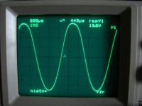
Input tube is a simple pentode EF86 – you probably know that simple pentodes in input is the beloved method of Andy Groves in all Audio Note amplifiers – which obtains the full voltage gain of amplifier. It is buffered from the double output 300B tubes thru a 5687 very strong double triode configured as simple voltage follower (0dB gain). The EF86 is AC coupled to 5687 thru a 15nF “mylar in oil” capacitor. The 3rd (suppressor) grid of EF86 it is connected to cathode which is biased by the appropriate 2.2KΩ resistor to GND and bypassed thru a 220μF capacitor. A 470nF “mylar in oil” huge capacitor connected across the 3rd suppressor grid and the 2nd screen grid eliminates the Miller phenomena. The two output tubes are of the brand “Full Music” equipped with solid carbon plates (300B/c). I selected these tubes for their ruggedness compared to mesh plate ones; we need as much as possible power because our speakers are some “heavy”. Plate voltage respect to GND is 450V while the voltage across plate – cathode is 393V as cathode is biased at 57V. The output transformer (made in Greece by G. Antoniadis laboratories - Thessaloniki) proven amazingly good, as under any output load the voltage drop of primary winding is just 7V. It stays cool (not heated) yet after 2 – 3 hours of operation. With an 8Ω non-inductive dummy load connected at output and with a sinus of 0.45Vrms as stimulus in input (that is the input sensitivity or the max signal for full output power) I measured with a DSO connected across the load a peak voltage of 13Vrms, stable, from 50 up to 2,500Hz. That means a maximum output power of 21.12Wrms. Without load the peak output voltage is 19.6Vrms. Later I did the usual bandwidth test according to EIA standards (output set at -3dB of its max value) to locate the -3dB points: The low limit is 12Hz and the high 22KHz, thus bandwidth = 12 – 22,000Hz. For the record, at 10KHz = 8.2Vrms (-0.8dB), at 20KHz = 6.6Vrms (-1.6dB), at 40KHz = 4.2Vrms (-6.6dB), at 60KHz = 2.48Vrms (-11dB) and finally at 100KHz = 0.86Vrms (-20dB).
The power supply includes a 400VA mains transformer. The HT voltage is rectified by a 5C3S (Russian military version of 5U4G and more rugged) and smoothed thru a “Π” filter composed from 3 nice Mundorf M-Lytic HV+ capacitors (those with 4 pins), Allen Bradley carbon composition resistors (can withstand better in high inrush current surge pulses than carbon film) and the huge 10H/310mA choke. Separate power supply is used for the 5687. Filament voltages for all tubes (except rectifier 5C3S) are DC stabilized via three LM1084 – 5A voltage regulators. Mains power consumption after a 30’ preheat time is stabilized at 1.2Aac. Output noise, though the whole device is still “bare” (cover plates and transformer covers are still in process) and so non screened, varies between 2mV to 4mV. I hope will drop down to 0.5mV after the shielding of everything.
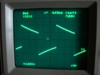
What impressed me from my first contact with a tube amplifier (I am a solid state guy for 35 years) is that: a tube amplifier actually does not clip the output signal be it so is overdriven. Being sure that its max output voltage capability is 13Vrms/8Ω I tried bigger sinus stimulus in input than the max 0.45Vrms. Of course it is obvious that the sinus signal starts to distort presenting a rounding and a small tilt in the “falling” edge of sinus but does not presents a hard clipping like in solid state amplifiers (the signal is “latched” at the level of supply rails and presents a straight “duty cycle” like in square waves) a thing that is very dangerous for the speakers. Instead this, the tube amplifier simply “rounds” the corners of a clipped signal. Output transformer also plays a role on this.
For audition tests, please don’t ask me. I like very much music of any kind (from rock up to classic, jazz, folk and anything sounds nice in my ears) and I hear every day enough hours. But to be focused on a sound device it should produce significant amounts of distortion! For that reason I entrust only what I can measure with my instruments and I study thoroughly the technology of electronic parts from active and passive components up to relays, switches and cables. For example, in this project I had contact with carbon composition resistors for first time in my life. Also with “Mylar in Oil” foil capacitors, tantalum resistors, those M-Lytic HV+ of Mundorf, UPOCC Silver wire etc, etc.
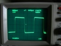
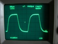
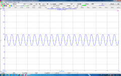
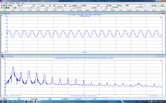
To the present I attach 4 screen shots I taken from my DSO that show the behavior of amplifier in square waves at the 4 most common frequencies: 100Hz, 1KHz, 10KHz and 20KHz. Also a sinus that shows the peak voltage amplitude. In all measurements a 8Ω dummy load was connected at output. When I receive back my workstation PC I will make and the FFT analysis (how much is the 2nd harmonic?) and I will upload all schematics. Pictures of device in few days when chassis will be completed.
I will appreciate very much any comment and any suggestion. Thank you very much.
Three days ago I finished my first tube project. So, you could consider me as a newbie in tubes. The project is a single ended class A mono power amplifier without feedback. Actually it is a modified version of “Glass House 300Bse” stereo amplifier circuit designed by Andy Groves (Audio Note). In general I used the same circuitry. Major changes I did was the second 300B paralleled with the single of original circuit, the different EI output transformer equipped with a special core of 17,000 Gauss rated at 100W and 1,500Ω primary winding. Also a huge choke of 10H/310mA. At the moment I haven’t possibility to upload the schematic (with voltages marked at all critical points) because my main PC – where the plans are stored – was damaged and is at service now.
So I will make a brief description – though I think many of you have knowledge – for the rest:
Input tube is a simple pentode EF86 – you probably know that simple pentodes in input is the beloved method of Andy Groves in all Audio Note amplifiers – which obtains the full voltage gain of amplifier. It is buffered from the double output 300B tubes thru a 5687 very strong double triode configured as simple voltage follower (0dB gain). The EF86 is AC coupled to 5687 thru a 15nF “mylar in oil” capacitor. The 3rd (suppressor) grid of EF86 it is connected to cathode which is biased by the appropriate 2.2KΩ resistor to GND and bypassed thru a 220μF capacitor. A 470nF “mylar in oil” huge capacitor connected across the 3rd suppressor grid and the 2nd screen grid eliminates the Miller phenomena. The two output tubes are of the brand “Full Music” equipped with solid carbon plates (300B/c). I selected these tubes for their ruggedness compared to mesh plate ones; we need as much as possible power because our speakers are some “heavy”. Plate voltage respect to GND is 450V while the voltage across plate – cathode is 393V as cathode is biased at 57V. The output transformer (made in Greece by G. Antoniadis laboratories - Thessaloniki) proven amazingly good, as under any output load the voltage drop of primary winding is just 7V. It stays cool (not heated) yet after 2 – 3 hours of operation. With an 8Ω non-inductive dummy load connected at output and with a sinus of 0.45Vrms as stimulus in input (that is the input sensitivity or the max signal for full output power) I measured with a DSO connected across the load a peak voltage of 13Vrms, stable, from 50 up to 2,500Hz. That means a maximum output power of 21.12Wrms. Without load the peak output voltage is 19.6Vrms. Later I did the usual bandwidth test according to EIA standards (output set at -3dB of its max value) to locate the -3dB points: The low limit is 12Hz and the high 22KHz, thus bandwidth = 12 – 22,000Hz. For the record, at 10KHz = 8.2Vrms (-0.8dB), at 20KHz = 6.6Vrms (-1.6dB), at 40KHz = 4.2Vrms (-6.6dB), at 60KHz = 2.48Vrms (-11dB) and finally at 100KHz = 0.86Vrms (-20dB).
The power supply includes a 400VA mains transformer. The HT voltage is rectified by a 5C3S (Russian military version of 5U4G and more rugged) and smoothed thru a “Π” filter composed from 3 nice Mundorf M-Lytic HV+ capacitors (those with 4 pins), Allen Bradley carbon composition resistors (can withstand better in high inrush current surge pulses than carbon film) and the huge 10H/310mA choke. Separate power supply is used for the 5687. Filament voltages for all tubes (except rectifier 5C3S) are DC stabilized via three LM1084 – 5A voltage regulators. Mains power consumption after a 30’ preheat time is stabilized at 1.2Aac. Output noise, though the whole device is still “bare” (cover plates and transformer covers are still in process) and so non screened, varies between 2mV to 4mV. I hope will drop down to 0.5mV after the shielding of everything.
What impressed me from my first contact with a tube amplifier (I am a solid state guy for 35 years) is that: a tube amplifier actually does not clip the output signal be it so is overdriven. Being sure that its max output voltage capability is 13Vrms/8Ω I tried bigger sinus stimulus in input than the max 0.45Vrms. Of course it is obvious that the sinus signal starts to distort presenting a rounding and a small tilt in the “falling” edge of sinus but does not presents a hard clipping like in solid state amplifiers (the signal is “latched” at the level of supply rails and presents a straight “duty cycle” like in square waves) a thing that is very dangerous for the speakers. Instead this, the tube amplifier simply “rounds” the corners of a clipped signal. Output transformer also plays a role on this.
For audition tests, please don’t ask me. I like very much music of any kind (from rock up to classic, jazz, folk and anything sounds nice in my ears) and I hear every day enough hours. But to be focused on a sound device it should produce significant amounts of distortion! For that reason I entrust only what I can measure with my instruments and I study thoroughly the technology of electronic parts from active and passive components up to relays, switches and cables. For example, in this project I had contact with carbon composition resistors for first time in my life. Also with “Mylar in Oil” foil capacitors, tantalum resistors, those M-Lytic HV+ of Mundorf, UPOCC Silver wire etc, etc.
To the present I attach 4 screen shots I taken from my DSO that show the behavior of amplifier in square waves at the 4 most common frequencies: 100Hz, 1KHz, 10KHz and 20KHz. Also a sinus that shows the peak voltage amplitude. In all measurements a 8Ω dummy load was connected at output. When I receive back my workstation PC I will make and the FFT analysis (how much is the 2nd harmonic?) and I will upload all schematics. Pictures of device in few days when chassis will be completed.
I will appreciate very much any comment and any suggestion. Thank you very much.
Attachments
Last edited:
Schematics 1
Hello
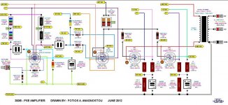
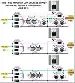
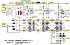
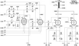
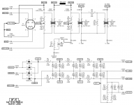
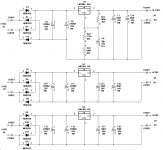
Here are attached the schematics of Power Supplies. The HV marked is for the high voltages while the LV marked is for the tube filaments. Also the schematic of amplifier. All schematics are presented in artistic mode but the value and the identity of each device is the true, as well all voltage markings. All measurements have taken with the mains voltage stabilized at 228Vac thru an autotransformer which is continuously callibrated by a microcontroller to the preset value, thus is not a simple variac. Because the poor resolution of pictures i also attach these in pdf format. You can open the pdf files to see most clearly the schematics.
Thank you.
Hello
Here are attached the schematics of Power Supplies. The HV marked is for the high voltages while the LV marked is for the tube filaments. Also the schematic of amplifier. All schematics are presented in artistic mode but the value and the identity of each device is the true, as well all voltage markings. All measurements have taken with the mains voltage stabilized at 228Vac thru an autotransformer which is continuously callibrated by a microcontroller to the preset value, thus is not a simple variac. Because the poor resolution of pictures i also attach these in pdf format. You can open the pdf files to see most clearly the schematics.
Thank you.
Attachments
Hi,
congratulations for finishing your project!
Schematics are a little hard to read, but i think i understand the amp part. Well, the way G2 and G3 of EF86 are connected is new to me and i would like to understand it better. In my builds it is connected "normally" as pentode with some nfb for lower distortion (it sounds a little edgy without it), or as triode without nfb.
If there is enough gain you could try some nfb around EF86, it might sound better this way.
Cheers
Hi,
congratulations for finishing your project!
Schematics are a little hard to read, but i think i understand the amp part. Well, the way G2 and G3 of EF86 are connected is new to me and i would like to understand it better. In my builds it is connected "normally" as pentode with some nfb for lower distortion (it sounds a little edgy without it), or as triode without nfb.
If there is enough gain you could try some nfb around EF86, it might sound better this way.
Cheers
Thank you so much for your kind words and your comments GlowSignal !
You are right about the unusual connection of G2 and G3, it is this huge 0.47μF "Mylar in Oil" capacitor connected between them. I have seen in Philips datasheet the usual way of connecting G2 to Gnd thru a 0.05μF cap.
EF86 works as a voltage gain stage. Looking at the Philips datasheet and taking into account the given values of anode - cathode - G2 resistors and the 217V anode voltage, this tube should work with Av = 170. With the given input sensitivity of 0.45Vrms, Av = 76Vrms that exceeds the max output of 44Vrms given by Philips. So the required gain is fulfilled. BTW EF86 has much higher gain than any triode but needs some special precaution due to its sensitivity.
In other products of Audio Note, like the kits "Legend monoblock" and "Interstage monoblock", Andy Groves again makes use of a pentode in input, this time a 6SH7. In the "Legend" the 6SH7 drives directly the two output 300B tubes and again Andy has connected a 0.47μF cap between G2 and G3. In the "Interstage" the 6SH7 drives the two 300B output tubes thru an interstage transformer and in this design Andy does not use this 0.47μF cap accross G2 and G3.
From my solid state experience i know very well that each voltage gain stage presents large ammounts of Miller capacitance which is translated in overshoot and oscillations in the collector (anode for tubes) of VAS transistor. To eliminate it, we connect a "Miller compensation" capacitor of some pF (usually 15 to 100pF) accross collector and base. I think that Andy makes the same by inserting the 0.47μF cap accross G2 and G3, while in the "Interstage monoblock" Miller capacitance is eliminated by the primary winding (is a good coil) of interstage transformer so the cap accross G2 and G3 is absent. I am not sure for the above described, but in my project i tried to remove the 0.47μF cap and i had big oscillations from 500Hz and above. For that reason exactly i make the tests with square waves that i presented in my first post. You can see that all square waves are clean without any overshoot.
By sure the 0.47μF cap offers a form of feedback. I don't know what kind of feedback you mean exactly. Please advise me, and GREAT THANKS AGAIN.
Last edited:
Square Waves
For 30 years, i allways use square waves to test any of my solid state projects. The same i did and in my first tube project, you can see the results in the screen shots of first post. The use of a square wave as stimulus in input, it can reveals many usefull informations about the circuitry of project. Ringing, overshoot and oscillations show a bad compensation of Miller capacitance of the Voltage Gain Stage. It also shows a great instabillity of amplifier that is mandatory, especially in single ended without feedback tube designs. Negative feedback offers some form of protection against instability and its absence is a great risk for the circuit. A sinus wave used as stimulus can not reveals these oscillations or overshoot, if exist. I have seen in some tube threads screen shots from oscilloscope that show these ringings. For that reason we use a compensation foil capacitor of some nF arround input tube, either connected to Gnd or accross G2 (screen grid) and G3 (suppressor grid). I think that this capacitor offers some form of feedback from mid to high frequencies in input tubes, especially in pentodes which offer very high voltage gain so are very sensitive in external RFI, EMI etc. infections.
Thank you for your attention.
Hello
Here are attached the schematics of Power Supplies. The HV marked is for the high voltages while the LV marked is for the tube filaments. Also the schematic of amplifier. All schematics are presented in artistic mode but the value and the identity of each device is the true,...
These "artistic" schematics are VERY hard to follow. Wires are crossed up inside the very small tubes symbols.
I looked at the scope shots. I'm betting a few percent harmonic distortion in the single digit range. This is I think the goal of both these SET amps as well as guitar amps - to add a bit of distortion. How much is a mater of taste.
Looking forward to the FFT numbers
Great thanks Chris for your comments! Are so precious to me, though i have enough experience with electronics design that is my first tube project and i feel some stressed, nothing more.
I ask your forgiveness for the "artistic" schematics, only these i saved in my old PC (i use this at the moment) before my good PC was fried! It needs new power supply and motherboard, i will have it ready in 3 days, the original and clear schematics are stored on it and i will upload these immediatelly. Also i will make the FFT analysis.
I appreciate very much your incisive look, that is what i expected, a man who can estimate the performance of a circuit from the DSO screen shots of square waves! It is obvious that you are a true audio electronics engineer - designer probably working in one of these famous Hi-End audio USA companies! Thank you so much!
For the record now, from the 10KHz and 20KHz waves shape it is obvious that the EF86 is somehow overcompensated. For that reason the -3dB upper frequency limit lies at 22KHz. If i used a smaller cap than the 470nF monster, say 220nF, i think that i could obtained a -3dB upper frequency limit at 40KHz but... in the cost of increased distortion. I know the concept behind tube amplifiers, is the high level of 2nd harmonic (mosfets also obtain a signifficant ammount of it compared to "poor" BJTs) that sounds nicelly in the ears of people. So i try to do a compromise between conflicting things. I don't like e.g. a 10% THD yet at full power! I could accepted a 5 to 6% THD as much. The amplifier is addressed for a home Hi-Fi music system, not for electric guitar, i know from these things as i was working enough years in live stages. The lead guitar performer likes a... ton of distortion at 130dBSPL in bass frequencies where the thing is technically difficult to obtained. It is mostly a mater of speakers, not so much of the tube head!
Another one issue is the output power. These 300B/c are amazingly strong. I tried them with 500V on plates, and i got almost 15Vrms accross the 8Ω dummy load just before clipping occurs and that means an output power of 28 clear American Wrms
") (i allways use the EIA methods and standards). OTOH, i really dither to push so hard the output 300B/c, i still don't have experience of their service life, just that are stronger compared to mesh plate ones.
(i allways use the EIA methods and standards). OTOH, i really dither to push so hard the output 300B/c, i still don't have experience of their service life, just that are stronger compared to mesh plate ones.Thank you again Chris.
Last edited:
... a man who can estimate the performance of a circuit from the DSO screen shots of square waves! It is obvious that you are a true audio electronics engineer - designer probably working in one of these famous Hi-End audio USA companies!...
No, nothing like that. I have an old Tek, 365 analog scope and an older Heathkit distortion analyzer that has an analog meter that reads out in THD. No computers or FFT inside it's all done with vacuum tubes. This simple meter is useless with modern solid state amps as they all read "zero" THD but works well for tube amps with the NFB loop open. I think the meter is a valuable tool for breadbroarding vacuum tube based audio circuits and checking components.
If you see a sine wave on the scope and have an analog THD meter you can quickly learn to judge THD percent based on the shape of the sine wave. I see blunted tops on the waves but not really bad ones.
But the best use of a THD meter is the "residuals" output. The meter can subtract out the fundamental and give the remaining signal. Then you put this on a scope and you can see only the distortion. It is easy to learn to see the cause by looking.
You can do all of this on a computer too but I hate to connect a computer to 400 volt tubes. If I do that enough times I'll cross up some wires
Clear schematics & valid voltages
My workstasion PC is again in order repaired and upgraded with new AeroCool PS, Asus M/B, Intel i3 3.4G CPU and 8GB RAM! Though the expense was big (340 Euro) for the difficult times we pass in Greece i finally am happy. The worst is that the PC damage (fried Power Supply and M/B) caused from bad luck, i did a measurement in the output of power resistor after the cathode of rectifier 5C3S (480V) and the probe of multimeter was sliding on chassis causing a short circuit. My PC was in operation and fried . Probably the 480V HT passed thru the mains earth conductor to PC. BTW this 5C3S proved a nonster! With its solid carbon plates it doesn't give a damn about any short-circuit. The same the MILLS 50W cathode resistor!
Well, as i promised i attach the actual schematics with valid voltage marked on each point. Tommorow i will make the FFT analysis of amplifier and i will post the results.
Fotis
My workstasion PC is again in order repaired and upgraded with new AeroCool PS, Asus M/B, Intel i3 3.4G CPU and 8GB RAM!
Though the expense was big (340 Euro) for the difficult times we pass in Greece i finally am happy. The worst is that the PC damage (fried Power Supply and M/B) caused from bad luck, i did a measurement in the output of power resistor after the cathode of rectifier 5C3S (480V) and the probe of multimeter was sliding on chassis causing a short circuit. My PC was in operation and fried . Probably the 480V HT passed thru the mains earth conductor to PC. BTW this 5C3S proved a nonster! With its solid carbon plates it doesn't give a damn about any short-circuit. The same the MILLS 50W cathode resistor!Well, as i promised i attach the actual schematics with valid voltage marked on each point. Tommorow i will make the FFT analysis of amplifier and i will post the results.
Fotis
Attachments
Last edited:
some first pictures
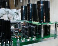
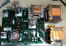
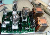
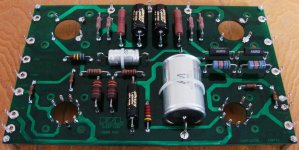
Though the amplifier is still not completed, i attach two general view pictures before the wiring and one that shows a detail of HT power supply pcb stacked with long spacers on the 5687 tube power supply pcb.
Though the amplifier is still not completed, i attach two general view pictures before the wiring and one that shows a detail of HT power supply pcb stacked with long spacers on the 5687 tube power supply pcb.
Attachments
Home made PCBs
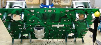
Here some pictures that show the proccess of main pcb step by step:
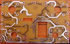
1. The pcb is drilled, cleaned and tinned with a thick layer of Radiel-Fondam Sn96-Ag4 solder wire.
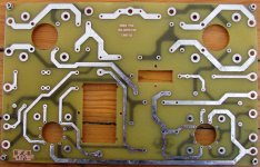
2. The pcb is double sided, here the solder side.
3. The pcb is sprayed with green protective laquer. Solder lugs are mounted with copper rivets and then soldered on the tracks. Collar sleeves are firstly punched to be stable and then are soldered. Both are "Ettinger" silver plated. I use collar sleeves as spacers for the parts to not touch the pcb surface.
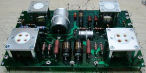
4. The pcb is assempled, all parts are of first quality.
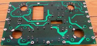
5. Here the CMC teflon - gold tube sockets firstly are mounted on home made 4mm alu plates, then the pcb is fixed with Φ4 spacers between tube bases. These tube bases are screwed directly on bottom cover of amplifier and are very solid, tube sockets are not solrered directly to pcb. To this i use small pieces from solid silver wire.
6. A picture of pcb from underneath, you could understand better the concept of tube bases.
Here some pictures that show the proccess of main pcb step by step:
1. The pcb is drilled, cleaned and tinned with a thick layer of Radiel-Fondam Sn96-Ag4 solder wire.
2. The pcb is double sided, here the solder side.
3. The pcb is sprayed with green protective laquer. Solder lugs are mounted with copper rivets and then soldered on the tracks. Collar sleeves are firstly punched to be stable and then are soldered. Both are "Ettinger" silver plated. I use collar sleeves as spacers for the parts to not touch the pcb surface.
4. The pcb is assempled, all parts are of first quality.
5. Here the CMC teflon - gold tube sockets firstly are mounted on home made 4mm alu plates, then the pcb is fixed with Φ4 spacers between tube bases. These tube bases are screwed directly on bottom cover of amplifier and are very solid, tube sockets are not solrered directly to pcb. To this i use small pieces from solid silver wire.
6. A picture of pcb from underneath, you could understand better the concept of tube bases.
Attachments
THD+N and Max Output at 8Ω
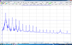
As i promised, just now i finished the FFT analysis of amplifier. The FFT analyzer software that i use is the "MI v3.2" of VIRTINS TECHNOLOGY and the interface an ASUS Xonar Essence STX pci express sound card. In the output of amplifier a 8Ω dummy load was connected. In general i got a max power of 20Wrms/8Ω with 6.5% THD+N "A-weighted".
Attached are the plots both as pictures and in pdf for better analysis.
Attachments
Last edited:
Correction!
In the above plots, the probe calibration factor was placed from mistake at 3.
See please on the top bar in "Probe" box. It should be noted that the sound card is thoroughly callibrated with the aid of an external precision function generator and a DSO. That is obvious again on the top bar:
"+/-2.94444".
So the real RMS value of signal is:
(19.8Vrms X 2) / 3 = 39.6 / 3 = 13.2Vrms
This max value of 13.2Vrms is also verified by the 5th screen shot of oscilloscope that is attached in my first post.
OTOH the FFT analysis is not affected by the probe callibration factor, will be the same either at 1 or 2 or 3. So the values of THD, THD+N, SINAD, SNR and NL are TRUE and expressed in dBV scale so you could make your own TRUE Voltage calculations. Remember please that 0dBV = 1Vrms, so e.g. 2Vrms = 20 X (log 2) = +6dBV etc.
Another one example is shown in the above FFT plot where the foundamendal 1KHz test frequency has amplitude of +20dBV (the peak exceeds a little the +20dBV line). The given value of 13.2Vrms above corresponds to: 20 X (log 13.2) = 22.4dBV and that proves the reliability of measurement.
Forgive me for the mistake
Last edited:
Well Chris, your prediction based on the scope screen shots of my 1st post proved right! Indeed the THD at the max output power of 21.5Wrms/8Ω is just 6.5% as indicated in the FFT plot. You are a true master in audio electronics!I looked at the scope shots. I'm betting a few percent harmonic distortion in the single digit range.
Here is the results of FFT analysis that i did mainly because you asked them.Looking forward to the FFT numbers
Thank you and i am looking forward for your comments.
Frequency response
Though i did a lot of careful preparation today for the FFT analysis (measurement of a tube amplifier with 480V HT is enough risky for the sound card and in general for the PC, you know that i have personal experience) i forgot to do and the bandwidth measurement.
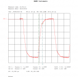
BTW there is an accurate method to do this with the DSO, using the "Gaussian system response function".
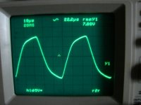
To this, we simply have to make a measurement of the rise time of a signal in the output of amplifier. The use of a 10KHz square wave as stimulus in input is necessary. Then, with the aid of the cursors of DSO we can measure the rise time of square wave at the output of amplifier.
With the use of Gaussian function BW = 0.34 /Tr where BW = bandwidth in Hz and Tr = Rise Time in sec, we can find the upper frequency limit of amplifier.
In the attached picture captured with DSO you can see that the Rise Time is dt = 12.3 μsec
So the bandwidth is: BW = 0.34 / (12.3 X 10^-6) = 27,642 Hz.
In the worst case of a small shift of cursors from the nominal 90% of the output signal full swing the Rise Time would be 13μsec as much. In this case the upper frequency limit will be: BW = 0.34 / (13 X 10^-6) = 26,153 Hz which is not so big reduction.
For the record, in my solid state projects and using exclusivelly BJT transistors i usually get Rise Times from 0.8 up to 1.2 μsec as much.
THANK YOU SO MUCH FOR YOUR ATTENTION! (I don't have nothing better to do at this moment)
Though i did a lot of careful preparation today for the FFT analysis (measurement of a tube amplifier with 480V HT is enough risky for the sound card and in general for the PC, you know that i have personal experience) i forgot to do and the bandwidth measurement.
BTW there is an accurate method to do this with the DSO, using the "Gaussian system response function".
To this, we simply have to make a measurement of the rise time of a signal in the output of amplifier. The use of a 10KHz square wave as stimulus in input is necessary. Then, with the aid of the cursors of DSO we can measure the rise time of square wave at the output of amplifier.
With the use of Gaussian function BW = 0.34 /Tr where BW = bandwidth in Hz and Tr = Rise Time in sec, we can find the upper frequency limit of amplifier.
In the attached picture captured with DSO you can see that the Rise Time is dt = 12.3 μsec
So the bandwidth is: BW = 0.34 / (12.3 X 10^-6) = 27,642 Hz.
In the worst case of a small shift of cursors from the nominal 90% of the output signal full swing the Rise Time would be 13μsec as much. In this case the upper frequency limit will be: BW = 0.34 / (13 X 10^-6) = 26,153 Hz which is not so big reduction.
For the record, in my solid state projects and using exclusivelly BJT transistors i usually get Rise Times from 0.8 up to 1.2 μsec as much.
THANK YOU SO MUCH FOR YOUR ATTENTION! (I don't have nothing better to do at this moment
)Attachments
Last edited:
Thank you so much for your kind words and your comments GlowSignal !
You are right about the unusual connection of G2 and G3, it is this huge 0.47μF "Mylar in Oil" capacitor connected between them. I have seen in Philips datasheet the usual way of connecting G2 to Gnd thru a 0.05μF cap.
EF86 works as a voltage gain stage. Looking at the Philips datasheet and taking into account the given values of anode - cathode - G2 resistors and the 217V anode voltage, this tube should work with Av = 170. With the given input sensitivity of 0.45Vrms, Av = 76Vrms that exceeds the max output of 44Vrms given by Philips. So the required gain is fulfilled. BTW EF86 has much higher gain than any triode but needs some special precaution due to its sensitivity.
In other products of Audio Note, like the kits "Legend monoblock" and "Interstage monoblock", Andy Groves again makes use of a pentode in input, this time a 6SH7. In the "Legend" the 6SH7 drives directly the two output 300B tubes and again Andy has connected a 0.47μF cap between G2 and G3. In the "Interstage" the 6SH7 drives the two 300B output tubes thru an interstage transformer and in this design Andy does not use this 0.47μF cap accross G2 and G3.
From my solid state experience i know very well that each voltage gain stage presents large ammounts of Miller capacitance which is translated in overshoot and oscillations in the collector (anode for tubes) of VAS transistor. To eliminate it, we connect a "Miller compensation" capacitor of some pF (usually 15 to 100pF) accross collector and base. I think that Andy makes the same by inserting the 0.47μF cap accross G2 and G3, while in the "Interstage monoblock" Miller capacitance is eliminated by the primary winding (is a good coil) of interstage transformer so the cap accross G2 and G3 is absent. I am not sure for the above described, but in my project i tried to remove the 0.47μF cap and i had big oscillations from 500Hz and above. For that reason exactly i make the tests with square waves that i presented in my first post. You can see that all square waves are clean without any overshoot.
By sure the 0.47μF cap offers a form of feedback. I don't know what kind of feedback you mean exactly. Please advise me, and GREAT THANKS AGAIN.
Hi,
Rg2 and Cg2 in classic connection take care of miller capacitance, serve against local nfb and smooths G2 voltage.
I think your distortion figures are pretty high, no? For mic preamps (which is what i mostly build) i tend to use global nfb into EF86 cathode to get distortion low. As your amp is easy to modify you could play with local nfb around EF86 and see how it reacts. I know for certain that EF86 without any nfb sounds pretty edgy to me because of distortion, this is why i would advise to make some experiments. And distortion i'm talking about can not only be heard, but also meassured
CCS would work for this, here you can see distortion P.Millet got with and without 6dB nfb using CCS:
http://www.pmillett.com/DCPP.htm
There is also global nfb and other things, others might give you better ideas of possibilities you have here.
Cheers
Last edited:
Hi,
Rg2 and Cg2 in classic connection take care of miller capacitance, serve against local nfb and smooths G2 voltage.
I think your distortion figures are pretty high, no? For mic preamps (which is what i mostly build) i tend to use global nfb into EF86 cathode to get distortion low. As your amp is easy to modify you could play with local nfb around EF86 and see how it reacts. I know for certain that EF86 without any nfb sounds pretty edgy to me because of distortion, this is why i would advise to make some experiments. And distortion i'm talking about can not only be heard, but also meassured
CCS would work for this, here you can see distortion P.Millet got with and without 6dB nfb using CCS:
DCPP Amp
There is also global nfb and other things, others might give you better ideas of possibilities you have here.
Cheers
Thank you so much Glowsignal for your comments and advices. Though i am not sure for the way to obtain nfb around EF86. I've tried some smaller caps in the place of this 470nF monster but i didn't obtained nothing. With 22nF the square wave remains almost same. I removed completelly the cap and i got lot of overshoot and oscillations. I think the 470nF is pretty good calculated by Andy Groves of Audio Note.
Regarding global nfb, i can't say nothing because the demand of the man for which i built this amplifier, it is not mine. He asked me a SET power amplifier without feedback.
For the CCS i have to study the issue of how can be applied in tubes. I have enough experience with CCS, i use them in excess in my solid state projects, they remove completelly the remaining ripple on power supply rails after rectification from the signal proccessing stages, the E-B and C-B juntions of a BJT are perfect barriers for ripple noise. But for tubes... i am still newbie.
By any way i will try in other project these concepts you mentioned.
Regarding THD and THD+N, really i don't know if is big. I also could not make comparisson with these really nice circuits of P. Millet (THANK YOU FOR THE LINK). Because in mine case the FFT shows the THD+N at full output power (21.5Wrms/8Ω) while all THD (Noise is not included) FFT analyses of P. Millet are taken at 1Wrms/8Ω. The difference in measurement set up is very big, i have to make again a FFT analysis with 1Wrms/8Ω output for a straight comparisson with this of P. Millet.
Square wave response of P. Millet amplifier is almost the same - regarding Rise Times - with mine amplifier both in 1KHz and 10KHz. Mine amplifier additionally does not presents any overshoot or oscillation compared to P. Millet (which are also negligible, i am not a freak!). For the frequency response as well, mine SET obtains better high frequency -3dB point compared to the P. Millet version without global feedback.
There are many points for analysis, at the moment is impossible a straight comparisson. The designs are completelly different. By any way THANK YOU AGAIN for the advices and the constructive discussion.
Do you know that a guy told me that had obtained a SET amplifier with a single 300B in output that gives a max output of 16Wrms/8Ω from 20 - 20,000Hz (+/-0.1dB) with 10% THD and that its -3dB limit lies at 40KHz? Is it possible?
Last edited:
Hi,
..
I think your distortion figures are pretty high, no? For mic preamps (which is what i mostly build) i tend to use global nfb into EF86 cathode to get distortion low. As your amp is easy to modify you could play with local nfb around EF86 and see how it reacts. I know for certain that EF86 without any nfb sounds pretty edgy to me because of distortion, ...
Cheers
I guessed from the rounded sine waved shown here a few days ago that he'd have THD in the mid single digit range. But is that "high". It depends on the goal. I think people who build single ended triode amps with no NFB want the hear some distortion (a.k.a. "tube sound") However what most are looking for is 2nd harmonic. I think if the EF86 is cleaned up a little by use of a few dB of local feedback thn all the remaining distortion is in the power tubes and it will likely be 2nd. As is i appears you are getting distorted distortion, which is always (I think?) higher order.
I like your description of the EF86 with no local NFB as "edgy". I build guitar amps and those will use a few
Here some pictures that show the proccess of main pcb step by step:
1. The pcb is drilled, cleaned and tinned with a thick layer of Radiel-Fondam Sn96-Ag4 solder wire.
2. The pcb is double sided, here the solder side.
3. The pcb is sprayed with green protective laquer. Solder lugs are mounted with copper rivets and then soldered on the tracks. Collar sleeves are firstly punched to be stable and then are soldered. Both are "Ettinger" silver plated. I use collar sleeves as spacers for the parts to not touch the pcb surface.....
You do some very nice looking and detailted work. I like to use "turrets". You call them "collar sleeves" but they look the same. I've never liked PCBs for tube equipment but "point to point" looks like a mess (when I do it.) so I like to compromise. Here is a photo of a power supply board I made for a stereo amp. It slightly resembles your method but I can make these in 30 minutes start to finish, literally. It is very fast. I draw the design on the fiberglass with a pencil them walk to the drill press, install the turrets then solder the parts.
https://www.dropbox.com/sh/vspqq9fbsptuoq9/6xIQUgVkhj
The box and chassis is a first "test fit". Neither is complete yet. But the PS board is done and will fit inside the chassis. Notice this board is a "wiring board" but it is just not a "printed wiring board". I use real wire.
- Status
- This old topic is closed. If you want to reopen this topic, contact a moderator using the "Report Post" button.
- Home
- Amplifiers
- Tubes / Valves
- My first tube project !