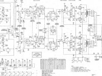
I have a working Harmon Kardon A500 integrated tube amplifier from the early 1960's that I want to try using it as a straight poweramp. (I already have a few good tube and solid state preamps.) My electronic schematic comprehension and disecting skills are only moderate. I could use some help with figuring how to electronically "separate" the poweramp section from the remainder of the integrated amplifier. Attached is a pdf of the full schematic.
Attachments
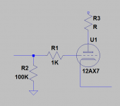
Disconnect the balance control from the 12AX7A grids, add a 1K grid stopper and 100K resistor to ground at each grid and run to a convenient set of RCA jacks on the back panel.
Best place to ground 100K resistors might be at the balance pot ground.
Do not remove V1, V2, or V3 as their filaments are part of the output stage bias arrangement. It is kind of clever and provides clean dc to the pre-amp and tone control stages, but the amplifier will not operate without them.
Make this reversible in case you ever decide to sell the amp.
Attachments
I have a working Harmon Kardon A500 integrated tube amplifier from the early 1960's that I want to try using it as a straight poweramp. (I already have a few good tube and solid state preamps.) My electronic schematic comprehension and disecting skills are only moderate. I could use some help with figuring how to electronically "separate" the poweramp section from the remainder of the integrated amplifier. Attached is a pdf of the full schematic.
You have a nice integrated amp. Please if you modify it, besure to make the modifications reversible. WHy not simply use it as-is. Leave the tone and balance controls centered and it will be a good power amp.
OK if you must hack good working gear what you need to do is feed the input signal to the grids of that 12AX7 tube (pins 2 and 7). To do that
1) Disconnect whatever is connected now
2) connect to ground via a 1Meg resister (we call this a grid leak resistor)
3) connect to the input jack via a (about) 10K resister in series. This resister will make a low-pass fitter to keep radio out of the amp.
The amp will not sound much different but you will have bypassed all of the controls
No, a 10k series resistor won't do much, but a capacitor at that location might be a good idea to block dc at the input. THAT would also make a lowpass filter with the 100k suggested by Kevin.
The 10K resistor combines with the Miller capacitance (interelectrode capacitance times the gain) in the tube. The 10K value is not critical and anything from about 68K to 10K would work. In fact in many cases zero Ohms will work. So I picked 10K as it does the least possible harm. You may need to go higher
You can put in a series cap if you need it. Let's hope your source does not have a DC bias on it and we can eliminate a coupling cap.
A series cap will not make a low pass filter. If makes a high pass filter. So if you do need that cap, make it big so that you don't cut off the bass frequencies.
Sorry, I mistyped. Series cap does indeed make a high pass filter.
I guess I'm more concerned with keeping DC out than RF, but I don't live under a transmitting tower") Seriously, I've never had a preamp put out RF, but if that's a concern then sure, a low pass resistor will do.
Seriously, I've never had a preamp put out RF, but if that's a concern then sure, a low pass resistor will do.
I guess I'm more concerned with keeping DC out than RF, but I don't live under a transmitting tower
Seriously, I've never had a preamp put out RF, but if that's a concern then sure, a low pass resistor will do.You show the 100k resistor to ground before the 1K series resistor tom the grid. ChrisA (below) seems to suggest that his recommended 1 meg resistor is direct from the grid to ground and 10k resistor is in series - between the input jack and the grid/100k resistor junction. So, I have 2 questions. When do you appear to wire your 2 resistors in reverse order from what ChrisA suggests? And, why are your values so different from his?I have a working Harmon Kardon A500 integrated tube amplifier from the early 1960's that I want to try using it as a straight poweramp. (I already have a few good tube and solid state preamps.) My electronic schematic comprehension and disecting skills are only moderate. I could use some help with figuring how to electronically "separate" the poweramp section from the remainder of the integrated amplifier. Attached is a pdf of the full schematic.
Just trying to understand.
Disconnect the balance control from the 12AX7A grids, add a 1K grid stopper and 100K resistor to ground at each grid and run to a convenient set of RCA jacks on the back panel.
Best place to ground 100K resistors might be at the balance pot ground.
Do not remove V1, V2, or V3 as their filaments are part of the output stage bias arrangement. It is kind of clever and provides clean dc to the pre-amp and tone control stages, but the amplifier will not operate without them.
Make this reversible in case you ever decide to sell the amp.
You show the 100k resistor to ground before the 1K series resistor to the grid. ChrisA (in a subsequent comment) seems to suggest that a 1 meg resistor is connected direct from the grid to ground and a10k resistor is wired in series - between the input jack and the grid/100k resistor junction. So, I have 2 questions.
Why do you appear to wire your 2 resistors in reverse order from what ChrisA suggests? And, why are your values so different from his?
Just trying to understand.
(Sorry about the 1st messed attempt to communicate this question!)
Pete
Matter of preference I suppose. I like lower value grid resistors. I generally use 1K grid stoppers as this with the tube's miller capacitance provides sufficient attenuation in the AM band that RFI is not usually a problem, and I am concerned about johnson (thermal) noise in input resistors in series with the signal source - in this case since it is line level it should not be critical.
Note that grid stoppers are usually placed right at the grid, and if placed before the grid resistor instead form one leg of a voltage divider which in some cases can be useful, and others not.
Note that grid stoppers are usually placed right at the grid, and if placed before the grid resistor instead form one leg of a voltage divider which in some cases can be useful, and others not.
You show the 100k resistor to ground before the 1K series resistor to the grid. ChrisA (in a subsequent comment) seems to suggest that a 1 meg resistor is connected direct from the grid to ground and a10k resistor is wired in series - between the input jack and the grid/100k resistor junction. So, I have 2 questions.
Why do you appear to wire your 2 resistors in reverse order from what ChrisA suggests? And, why are your values so different from his?
Just trying to understand.
(Sorry about the 1st messed attempt to communicate this question!)
Pete
It does not really matter. OK well maybe it does. There are two things we need to do
1) Connect the grid to ground. (called a grid leak resistor) To do this the order is not important at all. If the charge first flows through a 10K resistor then the 1M it is like a 1.01meg resister. And the value is not critital at all anything from about 470K to 2M is good. We use 1M mostly by convention. Some time we see volue control pots serving double duty as grid leak resistors. Any path to ground is fine as long as it is less than 2meg. A handy place to mount the grid leak resistor is directly across the input jack. This looks odd at first. Why wire a resistor across an RCA jack? You do it because it is easy and it fits there
2) We need series resistance for a "grid stopper" resistor. Electrically, in theory this can be any place but in real-world practice the best place is soldered directly to the tube socket with as short of a lead as possible. The reason is that wire acts like an antenna and the wire between the grid stop resister and the tube is "un-protected" by the resister. Soldering to the tube socket makes the antenna as short as possible.
So it does not matter except for making the "antenna" small.
Agreed. The important thing is to place the series resistor (grid stopper) as close to the tube as possible, usually right at the socket.
To elaborate on what Kevin said, when placing the stopper "before" the grid leak (resistor to ground), you are forming a voltage divider and you must consider the values. You will note that Kevin and Chris proposed different values, but in each case they are in the ratio of 100:1. Therefore there is negligible loss of signal either way. If, on the other hand, you chose your resistors as 10k and 100k, you would now lose 10% of the signal when placing the stopper before the leak. So you must pay attention to those implications.
To elaborate on what Kevin said, when placing the stopper "before" the grid leak (resistor to ground), you are forming a voltage divider and you must consider the values. You will note that Kevin and Chris proposed different values, but in each case they are in the ratio of 100:1. Therefore there is negligible loss of signal either way. If, on the other hand, you chose your resistors as 10k and 100k, you would now lose 10% of the signal when placing the stopper before the leak. So you must pay attention to those implications.
Here are two good articles on the subject. The 2nd one at aikensamps talks about the order of the resisters and why we need them. the first on has some lite math. Read both to understand this. Note the grid stoppers are used on all stages, even the power tubes typically have them.
Another reason for them is to prevent oscillation. this is why you see them used in non-input stages too.
The Valve Wizard
Grid Resistors
Another reason for them is to prevent oscillation. this is why you see them used in non-input stages too.
The Valve Wizard
Grid Resistors
- Status
- This old topic is closed. If you want to reopen this topic, contact a moderator using the "Report Post" button.
- Home
- Amplifiers
- Tubes / Valves
- Convert Integrated Tube Preamp to an amplifier