It's been a while since my last project. Now that I'm done with college I have a little more time for tinkering. I had to do this one by hand, the old school way. (Except the PSU which I designed with PSUDII). Any glaring errors before I start ordering parts?
Signal
LTP Curves
Input Curves
PSU to follow but it's nothing special. 282X -> 2xUF4007 -> 193M choke input, then another 10H 500 ohm choke for the B+2. The -80V supply will probably come from a tiny 56V Hammond from Mouser, then 187B56.
Signal
An externally hosted image should be here but it was not working when we last tested it.
LTP Curves
An externally hosted image should be here but it was not working when we last tested it.
Input Curves
An externally hosted image should be here but it was not working when we last tested it.
PSU to follow but it's nothing special. 282X -> 2xUF4007 -> 193M choke input, then another 10H 500 ohm choke for the B+2. The -80V supply will probably come from a tiny 56V Hammond from Mouser, then 187B56.
It is ") That and the 6AG5 should be pretty easily obtainable in NOS condition.
That and the 6AG5 should be pretty easily obtainable in NOS condition.
I could have gotten ~20V more swing from the LTP by giving it 8mA instead of 10 and increasing the plate resistors to 15K (iirc). However, I think they like a little more current, and the lower output impedance might help if I decide to triode-strap. The 10M45 is also probably happier at 10mA..
That and the 6AG5 should be pretty easily obtainable in NOS condition.I could have gotten ~20V more swing from the LTP by giving it 8mA instead of 10 and increasing the plate resistors to 15K (iirc). However, I think they like a little more current, and the lower output impedance might help if I decide to triode-strap. The 10M45 is also probably happier at 10mA..
Last edited:
Sorry, 230V on the top of the 6N1P is misleading. The supply is 430V, and it only loses 50V to the plate resistor, so that should say 380V instead. It's "230V effective" when using the curves to determine a load line, yes?
Your diagram has obvious mistakes.
The 6AG5 is triode connected to a 'current source' that is bypassed to ground through a 1uF capacitor - the way it is drawn, the plate load for this section is the 545ohm resistor. This will provide a lot of attenuation and distortion, not gain.
The bottom half 6N1P grid must not be connected to ground, since the top half is DC coupled to ~143V if you want this to work at all. This way the bottom half of the 6N1P is WAAAAY into cut-off (-140 something volts at G1) so no phase splitting.
The output tube bias network has a common flaw, namely if the wiper of the adjustment pots go open (which may happen during adjustment as they turn even on pots that normally seem to work OK), the tubes will be left with no negative bias, i.e. maximum current will flow.
Last edited:
Since you have a -80V supply for bias, why not use it for the LTP tail as well.
Because he wanted to omit the coupling capacitor?
Best regards!
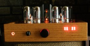
6L6GC's sounded good in both triode and UL connected with 6.6K outputs. I had 10 ohm resistors to ground on each of the cathodes to monitor the bias current with a bias monitor circuit. ( the leds in the pic)
I switched the outputs to 4.3K's and the 6L6GC's ran out of steam, swapped to 6550's and KT88's. No issue with enough neg bias available to throttle them back to 45ma.
Check your schematic on the cathode output connection....
I switched the outputs to 4.3K's and the 6L6GC's ran out of steam, swapped to 6550's and KT88's. No issue with enough neg bias available to throttle them back to 45ma.
Check your schematic on the cathode output connection....
Attachments
Because he wanted to omit the coupling capacitor?
Best regards!
Normally the grid of the lower 6N1P is biased with a 1M resistor from the grid of the upper 6N1P. The grid of the lower 6N1P is then 'grounded' for AC by using a suitable cap from grid to ground, which acts as a coupling cap as well.
Just added a random schematic from internet to illustrate the use of the 1M and cap described above.
At least that is what I learnt from earlier comments on these sort of schematics here at Diyaudio.
Attachments
Last edited:
Need way more than 50V across the 6N1P plate resistor if you are looking for anything like a linear swing of 90Vpp (+/-45V~)into the grids of your 6L6G. Not going to be very linear at all if you are forcing the LTP close to cut off.. Give yourself at least 3dB of additional linear headroom..
RE post 10, removing the 1Meg in parallel with input 100K Pot. I usually do that to protect against a loose wiper on the pot.
Sure, but you could switch the leads to make it the grid leak with the wiper on the input side.
If the pot gets intermittent it's time to change it anyway.


Sure, but you could switch the leads to make it the grid leak with the wiper on the input side.
If the pot gets intermittent it's time to change it anyway.
The wiper cannot be on the input side as then you have the entire pot in series with the input signal, and when the wiper is set to ground, you are short circuiting the input signal. The 1M on the wiper is sound design practise because of aforementioned wiper conduction. Even the best pots have variations in wiper to pot element resistance while they are being operated, especially with CD current going through the wiper contact (this is normally to be avoided or it will destroy the pot eventually). In a situation like on the schematic, this can happen if the input tube becomes gassy or develops excessive grid leak current for any reason - you will get a warning in form of a noisy pot rather than scraping booms from your loudspeaker. In some cases it is also advised if the pot is connected to the rest of the circuit with cables, especially in a DIY situation, where it might become disconnected. In other words, it's a really small price for a nice security feature.
The wiper cannot be on the input side as then you have the entire pot in series with the input signal, and when the wiper is set to ground, you are short circuiting the input signal. The 1M on the wiper is sound design practise because of aforementioned wiper conduction. Even the best pots have variations in wiper to pot element resistance while they are being operated, especially with CD current going through the wiper contact (this is normally to be avoided or it will destroy the pot eventually). In a situation like on the schematic, this can happen if the input tube becomes gassy or develops excessive grid leak current for any reason - you will get a warning in form of a noisy pot rather than scraping booms from your loudspeaker. In some cases it is also advised if the pot is connected to the rest of the circuit with cables, especially in a DIY situation, where it might become disconnected. In other words, it's a really small price for a nice security feature.
I'll stand corrected for the wiper on the input. If that overloads the output from the prevoius stage for some reason.
Last edited:
Normally the grid of the lower 6N1P is biased with a 1M resistor from the grid of the upper 6N1P. The grid of the lower 6N1P is then 'grounded' for AC by using a suitable cap from grid to ground, which acts as a coupling cap as well.
Just added a random schematic from internet to illustrate the use of the 1M and cap described above.
At least that is what I learnt from earlier comments on these sort of schematics here at Diyaudio.
This is an excellent example which also shows why the LTP in the original schematic benefits from a tail CCS. Since it is biassed by the top half grid being at roughly 140V, the common cathodes will normally be even more positive (as we want the grids to be negative biassed WRT cathodes), so there is ample 'room' for a CCS to operate.
A quick look at the figures on the top lefthand side of the schematic Erik provided shows a common problem with a resistor tail LTP - it is not quite symmetrical (note different THDs), and in fact often needs slight adjustment of the plate resistor on one side to make the outputs exactly equal amplitude. This is because we would normally want the highest possible tail resistor, so that the cathode of one side of the LTP drives the cathode on the other side, with the least possible of this signal being lost to the tail resistor. Since the value of said resistor is determined by tail current, idealy we want the highest available voltage on it so that for a given current the resistance of the resistor is the largest possible - at the cost of more heat produced on the tail resistors.
The dynamic resistance of a CCS is quite large compared to any tail resistor in this situation, the current through it is by definition constant and no current is spent driving the CCS from the common cathode point of the LTP, hence the LTP outputs are precisely locked one to the other and always the same amplitude as long as their plate loads are the same. The only requirement is that the CCS needs to have a minimum voltage across it to operate correctly. Increasing the voltage across the CCS much more than that has no advantage, only generates more heat in the CCS (as the power dissipated on it is equal to CCS current x voltage across CCS).
Need way more than 50V across the 6N1P plate resistor if you are looking for anything like a linear swing of 90Vpp (+/-45V~)into the grids of your 6L6G. Not going to be very linear at all if you are forcing the LTP close to cut off.. Give yourself at least 3dB of additional linear headroom..
It may be even worse than that since the output winding is used as cathode feedback to the output tubes. The peak output voltage for full desired output power over 4 ohms should be added to the peak g1-to-cathode swing to get MINIMUM required swing from the driver stage. To get around all possible tolerances (and they always add unfavorably!) 30% more linear swing is highly desirable, which means a good 50% or more over the minimum before any signs of clipping from the driver... It might be a good idea giving the 6N1P stage as much power supply voltage as you can muster.
Also, very important, when the tubes are cold, there is no load current from the power supply which means no voltage reop across the RC filtering networks to the first stage. The plate of the 6AG5 will go nearly to the full power supply, whereas the cathodes of the 6N1P will stay close to 0V, giving it an initial 400V or so Vg1. It would be a godd idea to put a protection diode from G1 to K of the top half of the 6N1P to protect against positive Vg1. Correcting the G1 biassing of the bottom half like ErikdeBest sows in the attached schematic, will automatically take care of the bottom triode as well if the abovementioned diode is fitted.
- Status
- This old topic is closed. If you want to reopen this topic, contact a moderator using the "Report Post" button.
- Home
- Amplifiers
- Tubes / Valves
- New 6L6GC Project. DC -> LTP