As above, --
But, the question is, would one still invert the drive from the PI to the two Common-Cathode gain-stages between the PI and the O/P stage...?
The CC stages of course, Invert anyway, and being a little 'brain-dead' tonight, cant get my head around it......
I plan to experiment with a Screen-Drive Futterman and need much more drive volts than I can easily get from a normal concertina PI....
Yes--Its a PP amp. The 'Inverted-Futterman' uses the upper PI signal connected to the Lower O/P tube and vice-versa, while the PI ground is returned to the O/P--If you see what I mean!
But--As I have inverting amplifiers between the PI and the O/P stage, --do I still connect the PI in this way or do I connect 'straight' to the drivers and let the drivers do the 'inversion'...?
But--As I have inverting amplifiers between the PI and the O/P stage, --do I still connect the PI in this way or do I connect 'straight' to the drivers and let the drivers do the 'inversion'...?
What would you benefit from screen drive in an OTL? They are not lowZ as I understand it, haven´t tried them as CFs though. I can be wrong as I have not seen your circuit. If you want to go tetrodes you could go boosted triode instead, ie a lower Ua and an added Ua on top of the anode to Sg. An EL509 can then run at Ua 70V with an added 100V on top to the Sg. And you bring drive voltage down instead!
Secondly why should the concept with two gainstages inside the feedback loop be a good idea? Let the input stage be outside the loop instead.
If you compare an inverted (concertina) Futterman with a noninverted, the inverted already has 10dB NFB around the OP-stage and concertina.
A LTP does not seem to give the intended results when inverted.
Last edited:
If you want to go tetrodes you could go boosted triode instead, ie a lower Ua and an added Ua on top of the anode to Sg.
Sorry Alastair,
Should be: added Ug on top...
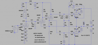
Something like this:
Attachments
better question is why build a Futterman at all?
it's really not a particularly good circuit, you can keep the output stage, but the rest is marginal, imo...
_-_-bear
Well--To be honest, I wasn't looking for views and Opinions on the Futterman scheme its merits or drawbacks.....
It was merely a simple question!
Adding a set of stages (basically one in each phase) between the PI and O/P ....
Do I Invert Or Not....?
Simple question!
I dunno! Guess I'll have to build it and find out myself failing any helpful replies!
For reference, PL509, screen-driven as C-F's, Drive up to 350V P-P, 200V Plate and OTL in format.
--Little to be gained in MO dropping the supplies to the O/P stage to only 70V.....
NFB whether global or local isn't the great enemy if done carefully and sparingly.....
It is known, that Screen Driven 'sweep-tubes' are extremely linear in their operation......
The CC stages of course, Invert anyway, and being a little 'brain-dead' tonight, cant get my head around it......
There is no answer to your question as it is no inverted Futterman when adding gainstages between the PI and the O/P.
Thought you liked low Ua as you ran 6C33C with cathode bias at 100V
.
Last edited:
Basically what revintage said... but I suspect your idea is to make the output tubes behave like followers WRT the phase splitter stage, not WRT their own drive (I guess you are looking at screen drive here). In this case, you would need to preserve the phase relationship between the output and the phase splitter, in order to provide the bootstrap feedback that makes the inverted futterman what it is. In other words, if your additional gain stage inverts, then the inputs to this gain stage, must be inverted in phase WRT phase splitter to preserve correct phase relationship. The bottom of the concertina still has to be referenced to the output, so the outputs of the concertina must be exchanged going to your inverting drivers, driver for the bottom tube must be from the bottom side of the concertina, not the top, to take care of the inversion in the driver.
Regarding lowering the supply to the output tubes - hardly little to be gained as the peak dissipation drops signifficantly. I actually like revintage's approach with an 'enhanced triode mode' strapped pentode - how much higher you can strap G2 depends on how much lower the plate can go relative to G2 before you get excessive current through G2, but there is quite a lot of space to play around with this in sweep tubes, since they were designed for that sort of thing.
I have discussed screen drive for OTLs in the other OTL thread. The problem with it is that it's almost too linear - the crossover region for class AB operation shrinks a lot (in classic OPT amps the plate standing current for optimal results can be as much as 10x lower for screen drive), and so does the alowable error in setting it, read: tubes must be well matched or separate AC and DC balancing must be provided, and this still leaves you with problems in adjustment as the tubes age, and worse - for sweep tubes - heat up. Of course, almost all of this can be circumvented by class A operation, but this would be unlikely in an OTL.
Which brings me to another problem with screen drive linearity - OTLs can exploit non-linearity of the transfer characteristic of the tube to operate in something like a geometric mean class A - this mode of operation does not require that the standing current is half of the maximum as is common in class A PP stages (rather much less instead), yet does not drive either half of the PP into cut-off, hence the standing power dissipation can be much lower than in conventional class A, yet there is no crossover region (one could say the whole operating range of currents and voltages for the amp is the crossover region). This is MUCH more difficult with screen drive precisely due to it's linearity.
Finally, totem-pole outputs (Futterman variations being of this kind) are not the most suited for any kind of drive where you have current driven into any control grid and out the cathode, because this current is passed through the load for top half of the output stage, and as far as the load is concerned, lost for the bottom half. In other words, you get a built-n asymmetry. This may or may not be significant depending on your tube choice.
Ah--Thanks Ilimzn....
Thats exactly the answers Ive been hoping for!
I think its worth playing round with a bread-board just for fun, and see the differences that are apparent with different bias-levels, and to a more conventional Futterman.
I concur about the asymetry of the O/P stage due to the 'lost' screen-current for the lower tube, Be interesting to see the effect of this in the real-world. A way of limiting the screen drive current may be needed--We see.....
My rough idea was the gain stages were to drive either CF's or MOSFETS to the g2 and use those to set the bias of the O/P pairs....
We see what happens anyway! This was just one of those 'mad-Monday' ideas,--You know the sort!
Hey Ilimzn,
All your negative expectations will probably be fullfilled about the grid drive. You will first of all need to run the tubes at so high Ua that there is no room for anything else than almost Class-B. It might have to do with the bias(as you describe) that distortion will not act as in conventional A and AB designs. Ie the, a little to, high distortion will not lineary be lower at lower signal levels.
So as we agreed before a very good solution is to go boosted triode. 4xEL509 will give far better results than 2x6C33C. With EL509 trioded at 170V they will be on par with the 6C33C. 70/100V Ua/+Us works OK for EL509 without risk for the to high Is. This will give a lot lower THD before feedback applied if we compare with the, to hard to handle, grid drive(or partly to any other configuration or tube). Also the low Ua gives us the opportunity to run at higher Iq giving us Class-A higher.
About adding two stages(must be differential) between the concertina and the O/P-stage to keep the phase right, this might be an idea. Unfortunately not in reality even if we also bootstrap the following stages. Only with the Concertina directly to the O/P-stage we get the low Zout expected from the inverted Futterman. If doing like the sandboys we could just add more GNFB to butter it up. But Zout isn´t all.
Instead of doing like they did in the early days of sand we can do like Otala and use local NFB together with lower GNFB.
All your negative expectations will probably be fullfilled about the grid drive. You will first of all need to run the tubes at so high Ua that there is no room for anything else than almost Class-B. It might have to do with the bias(as you describe) that distortion will not act as in conventional A and AB designs. Ie the, a little to, high distortion will not lineary be lower at lower signal levels.
So as we agreed before a very good solution is to go boosted triode. 4xEL509 will give far better results than 2x6C33C. With EL509 trioded at 170V they will be on par with the 6C33C. 70/100V Ua/+Us works OK for EL509 without risk for the to high Is. This will give a lot lower THD before feedback applied if we compare with the, to hard to handle, grid drive(or partly to any other configuration or tube). Also the low Ua gives us the opportunity to run at higher Iq giving us Class-A higher.
About adding two stages(must be differential) between the concertina and the O/P-stage to keep the phase right, this might be an idea. Unfortunately not in reality even if we also bootstrap the following stages. Only with the Concertina directly to the O/P-stage we get the low Zout expected from the inverted Futterman. If doing like the sandboys we could just add more GNFB to butter it up
. But Zout isn´t all. Instead of doing like they did in the early days of sand we can do like Otala and use local NFB together with lower GNFB.
Hey Ilimzn,
All your negative expectations will probably be fullfilled about the grid drive. You will first of all need to run the tubes at so high Ua that there is no room for anything else than almost Class-B. It might have to do with the bias(as you describe) that distortion will not act as in conventional A and AB designs. Ie the, a little to, high distortion will not lineary be lower at lower signal levels.
Actually it's not so much Ua, that could be low, but the drive voltage on G2 will have to be higher! In other words - lots of problems with constructing the driver and no payback regarding performance
So as we agreed before a very good solution is to go boosted triode. 4xEL509 will give far better results than 2x6C33C. With EL509 trioded at 170V they will be on par with the 6C33C. 70/100V Ua/+Us works OK for EL509 without risk for the to high Is. This will give a lot lower THD before feedback applied if we compare with the, to hard to handle, grid drive(or partly to any other configuration or tube). Also the low Ua gives us the opportunity to run at higher Iq giving us Class-A higher.
One of the biggest disadvantages of the 6S33S is the amount of heat it makes by only running it's heaters :|
To be clear I never intended to try G2 drive for an OTL, for the reasons I stated, I don't see any advantage and a lot of problems and disadvantages.
I will, however, look into the enhanced triode mode. There is still a problem with lowering Uak to near zero if there is no load, I will look into screen currents. I am more specifically interested in PL504s but the same principles apply.
About adding two stages(must be differential) between the concertina and the O/P-stage to keep the phase right, this might be an idea. Unfortunately not in reality even if we also bootstrap the following stages. Only with the Concertina directly to the O/P-stage we get the low Zout expected from the inverted Futterman. If doing like the sandboys we could just add more GNFB to butter it up
Actually the bootstrapping is the local feedback that makes the inverted Futterman output stage behave as a follower. The intermediate driver stages that provide extra gain to the control grids chosen (G2 in allistairE's case) restore the attocious 'follower' performance of G2 drive, The local feedback thus becomes less local, resulting on potential instability - so, one more drawback. But in my comment I was just exploring the idea, not that I would attempt it, honestly.
Instead of doing like they did in the early days of sand we can do like Otala and use local NFB together with lower GNFB.
No disagreement there!
- Status
- This old topic is closed. If you want to reopen this topic, contact a moderator using the "Report Post" button.
- Home
- Amplifiers
- Tubes / Valves
- Inv. Futterman with gain stages between PI and O/P?