Most important, as Kevinkr points out, dont let your signal ground from RCA to circuit ground go through chassie, give them an exclusive line to the starground point and separate that from chassie/earth ground if needed with diodes or caps. RCA ground must then be separated with plastic washers from chassie, otherwise theres a loop.
Twist filament wires better and hold them as far away from audio circutry as possible. Better long twisted lines in corners then short that interfere.
Refere filament to something like ground potential or higher. 100 or 200 k resistors works.
Your 6V6 cathode resistors is likely pretty hot an on the pic it liiks like they are gonna melt bypass caps.
Rotate one OPT 90 degrees or put them further away from each other. They most likely interfere with each others now.
But i bet its the first one that gives you the most audiable buzz atm.
best
Staffan
Thanks for all your suggestions. I plan to make the changes this weekend. The filament leads are original except for the preamp tubes. I had a thought just now. With the volume turned up there is no buzz. The volume pot is the only part not in the original schematic. And turned all the way up it has no effect. Maybe its the pot and its position that are the problem? I'll take it out and see what happens.
Thanks for all your suggestions. I plan to make the changes this weekend. The filament leads are original except for the preamp tubes. I had a thought just now. With the volume turned up there is no buzz. The volume pot is the only part not in the original schematic. And turned all the way up it has no effect. Maybe its the pot and its position that are the problem? I'll take it out and see what happens.
Not unlikely given the likely pick up mechanisms, but please do make the other suggested changes - the amplifier will perform, measure and sound significantly better.
It would help if you could diagram the volume pot input circuit.
When you installed it did you parallel it with the original 470K grid leak or use it to replace the grid leak?
What value is it?
Is it ahead of the grid leak or after the grid leak? Moot if it's gone.
Is the wiper the input side or the output side?
Shielded leads to it, from it, grounded where?
Is the ground end tied to the RCA jack ground or chassis?
Is the RCA jack chassis grounded or floating?
Thanks everyone for all the suggestions. I implemented them all and have a much better amp now. But I hate to say its not quite right yet. The amp sounds a bit too bright. And at higher volumes it is a little distorted. I think it may be there isn't quite enough feed back. I think the problem is the original draws feedback from the 16 ohm output, I don't have one. I'm drawing from the 8 ohm. Which I think means I have about 25% less voltage than the original design. At idle I measure 1.55ma drawn by the 12ax7s. So if I go down on the feedback resistor I will allow the 12ax7's to draw more current is that right? How can I increase feedback without increasing the current? Or is the feedback resistor not acting as a cathode resistor?
Thanks everyone for all the suggestions. I implemented them all and have a much better amp now. But I hate to say its not quite right yet. The amp sounds a bit too bright. And at higher volumes it is a little distorted. I think it may be there isn't quite enough feed back. I think the problem is the original draws feedback from the 16 ohm output, I don't have one. I'm drawing from the 8 ohm. Which I think means I have about 25% less voltage than the original design. At idle I measure 1.55ma drawn by the 12ax7s. So if I go down on the feedback resistor I will allow the 12ax7's to draw more current is that right? How can I increase feedback without increasing the current? Or is the feedback resistor not acting as a cathode resistor?
The feedback resistor IS part of the cathode circuit. But you can still make some adjustments to it for the amount of feedback.
The feedback R is 1K and on the 16R tap. That is identical to the OPT feedback system of the original ST-70. When the ST-70 Series 2 came out they moved the feedback connection to the 8R tap and changed the R to 680R. I'd find a 1K pot to experiment with replace the FB R with the best value from the pot ABOVE 680R.
I experienced about the same. My unproven feeling is that to high input signals in to the little 12AU7 exceeds its grid biasing limits in this configuration. Its designed for smaller input levels then modern signal sources is my guess. I havent prooved it yet but more feedback doesnt seem to help this and the above symptoms comes when I play material that is ripped with a clearly higher volume level.The amp sounds a bit too bright. And at higher volumes it is a little distorted.
Im planning to try another seesaw/paraphrase with local feedback and maybe 12AT7 instead. I will also give E90CC a try for fun (common cathode).
Please tell if you have found something that helps.
best
Staffan
Last edited:
Stajo,
I've gotten the amp finished and it really sounds nice. I'm using 6N6C Russian 6V6 variants and Hammond output transformers so I'm not sure if what I found will help. I used an 820pf cap for the feedback. After inserting a pot I found that the best sound was with about 600 ohms on the feedback resistor. I ended up using 560 ohms because I had them. I separated the preamp tube cathode resistors and stuck with the 1k but didn't ground them threw the output secondary. I also changed the output cathode resistors bypass cap to 33uf rather than the 50uf the schematic calls for. The Hammond's don't have the low frequency performance of the Dynacos. I tried a pair of 12AY7's in the front end but it didn't change the sound much and cost too much gain. I tried JJ 12AX7's and EH also. The Electro Harmonix sound better. My Snells are fairly inefficient but the amp had a nice rounded mid range, well defined highs and more bass than I would have expected from a ten watt amp. I think most of the problems were just not enough feedback.
Hope this helps, Kevin
Last edited:
Good to hear, congrats and thanks for the info!
Im also into tweaking the feedback but I'm a bitt puzzled about doing it on the 1k resistor since it also changes the working points of the splitter. My recent plan is to try to locate best value the feedback bypass cap with a scope and also set the splitters balance with the 47 k resistor first.
I might try with pot on the 1 k if that doesnt help. Thanks!
Staffan
Stajo,
I departed from the schematic and separated the feedback loop from the cathode resistor. I used the 1k resistor to ground the cathode to the star ground NOT through the output transformer. Then used the feedback loop on its own. The design was nice in that it could use a single loop for the cathode and feedback. But I suspect it only works with those transformers.
I departed from the schematic and separated the feedback loop from the cathode resistor. I used the 1k resistor to ground the cathode to the star ground NOT through the output transformer. Then used the feedback loop on its own. The design was nice in that it could use a single loop for the cathode and feedback. But I suspect it only works with those transformers.
Stajo,
I departed from the schematic and separated the feedback loop from the cathode resistor. I used the 1k resistor to ground the cathode to the star ground NOT through the output transformer. Then used the feedback loop on its own. The design was nice in that it could use a single loop for the cathode and feedback. But I suspect it only works with those transformers.
Racer,
If you have a 560R feedback from OPT to cathode you have just paralleled with the 1K and now have @ 400R (without my calc.) as cathode resistance instead of the original 1K.
I separated the preamp tube cathode resistors and stuck with the 1k but didn't ground them threw the output secondary.
racer; where do you insert the feedback? Can you do a little scetsh of the input cathode couplings?
Best regards
Staffan
Hey,
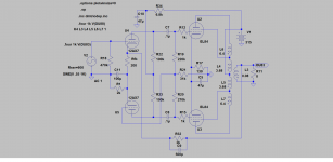
You seem a little lost here!
This way you can adjust NFB anyway you want it, without messing up the working points.
Use Rfb to adjust.
Working points are per the original circuit.
Also note, assymetry from the original driver signal must be adjusted. Make R19 220k and use a 100k trimmer for R21.
You seem a little lost here!
This way you can adjust NFB anyway you want it, without messing up the working points.
Use Rfb to adjust.
Working points are per the original circuit.
Also note, assymetry from the original driver signal must be adjusted. Make R19 220k and use a 100k trimmer for R21.
Attachments
Last edited:
- Status
- This old topic is closed. If you want to reopen this topic, contact a moderator using the "Report Post" button.
- Home
- Amplifiers
- Tubes / Valves
- Dynaco low Power Amp