More Hiss of the wiss
Hi
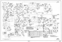
here is the schemo, I am 1/2 awake, lots of good ideas here.
NEVER USE 12ax7 tubes!
Use real Manly tubes like 6sn7, get big tone, have all the gain needed.
I tried a lot of combos, but ax7s a problem, as not that big tone sound, and way too much gain, so you have to use Neg feedback to control it.
Ax7s also can be hissy-wissy, if no neg feedback....
I work on, repair, and mod guitar amps etc..
here is a bad blog I have to destroy and put up again, Blogspot editor sucks weiners....Grid Leak
I ended up with one gain stage and a cathode follower out for just enough gain for my line stages
The old Juke bpx amp, dead quiet, fixed bias also!
All my Hi-Fi gear, systems were dead quiet, would surprise customers when they hear complete silence, then music blasts out...
I like Fish and other designs, don't mid me, old school.
Hi
here is the schemo, I am 1/2 awake, lots of good ideas here.
NEVER USE 12ax7 tubes!
Use real Manly tubes like 6sn7, get big tone, have all the gain needed.
I tried a lot of combos, but ax7s a problem, as not that big tone sound, and way too much gain, so you have to use Neg feedback to control it.
Ax7s also can be hissy-wissy, if no neg feedback....
I work on, repair, and mod guitar amps etc..
here is a bad blog I have to destroy and put up again, Blogspot editor sucks weiners....Grid Leak
I ended up with one gain stage and a cathode follower out for just enough gain for my line stages
The old Juke bpx amp, dead quiet, fixed bias also!
All my Hi-Fi gear, systems were dead quiet, would surprise customers when they hear complete silence, then music blasts out...
I like Fish and other designs, don't mid me, old school.
Attachments
No, you get minimum source resistance when the pot is at 1/2 voltage or -6dB attenuation. For a log pot this will of course be well above half travel.ElectricMan said:The reason for volume at 3/4 up is so the series resistance of the pot is at minimum.
I also, NEVER bypass preamp/line amp triode cathodes. I found the bypassing cathode Thang a complete myth. You get a "puddle" effect and hiss from the cap, as the pool of electrons in the cap are not quiet, like the water in a lake.
Also, the cap has a tendancy to make the gain stage more high freq gainy. I mod vintage guitar amps, a lot of Fenders etc., and I put 68 to 330 or more ohm resistors in series with the cathode caps to bring down Hsssssssssssss
Caps don't generate noticeable noise; resistors do. Bypassing a cathode resistor increases noise simply by increasing gain. You get more noise coming through from any earlier stages, and the stage itself (if a triode) loses local negative feedback which would otherwise reduce shot noise. Adding a small resistor in series with the cathode bypass cap gives you back some negative feedback so reducing stage noise and less gain for earlier stage noise.
Never follow audio myths! When used properly, as in some hi-fi amps, the 12AX7 gives low noise, low distortion and high gain. When used 'improperly', as in some guitar amps, the 12AX7 gives the sound that some people like. Problems arise when people try to use the 12AX7 for hi-fi without understanding how to do it properly.ElectricMan said:NEVER USE 12ax7 tubes!
Use real Manly tubes like 6sn7, get big tone, have all the gain needed.
Last edited:
Adding a small resistor in series with the cathode bypass cap gives you back some negative feedback so reducing stage noise and less gain for earlier stage noise.
Please clarified if I should
1) just add a small resistor in series with the cathode bypass cap only OR
2) should in series with the original cathode resistor and the bypass capacitor?
thanks!
Please clarified if I should
1) just add a small resistor in series with the cathode bypass cap only OR
2) should in series with the original cathode resistor and the bypass capacitor?
thanks!
Line of the stage more info
DF96 is correst, 'specially about guitar amps
What is a good circuit draw program for tube stuff???
I need one to do quick circuits for ex-plain
Put the buffer resistor in series with the cap positive to the cathode,
or
Put the resistor in series with the cathode, to the cap and cathode resistor in parallel.
I do this style for taming guitar amps. The cathode resistor is setting the base gain in each method, but having the buffer resistor in series with the cap positive to the cathode, means there is a small amount of pure resistance between the main audio and DC path and the cap.
The audio flows through pure resistance when not using a cap, so the response character of each stage is much more closely matched, as electroylitics are not that matched in how they pass audio.
Also, I found tubes like odd number values like 15k or 33 k grid resistors.
I used a resistor in series with both sides of coupling caps to "push back" against the cap and control it's response character. Pure series neg feedback is best to use in to out, so the whole circuit is stable without global neg feedback.
yes resistors create the current noise, and caps increase the sharpness, the top end Hissy, as the tube does not respond in a flat freq response way to a simple cathode bypass cap method.
Without a series grid resistor, or a tiny bit of resistance in series with the bypass cap, you get the puddle of electrons effect.
I am teasing about ax7s, but if you want a real big, deep sound stage, use big triodes, the bigger the plate structure is, the bigger the sound, like 300B and 847, same for line stage tubes.
That Fisher buffer is using a ax7 the right way, low gain, fab smooth tone....
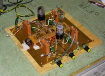
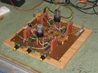
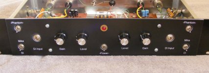
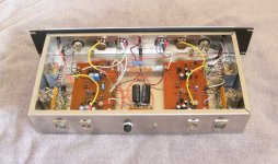
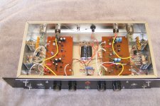
Here are two pics of a typical "Brute Force" 6sn7 line stage chassis being tested, my "woody" test bed.
Russian paper-oil caps, big carbon resistors, high idle current, big big sound.
Best is to be able to switch different tubes in/out, and even various coupling caps as then you can get the kind of response character for that special Jazz Sax solo etc. as one tube or coupling cap or circuit design is not best for everything, hopefully it will have a good sound that is enjoyable
DF96 is correst, 'specially about guitar amps
What is a good circuit draw program for tube stuff???
I need one to do quick circuits for ex-plain
Put the buffer resistor in series with the cap positive to the cathode,
or
Put the resistor in series with the cathode, to the cap and cathode resistor in parallel.
I do this style for taming guitar amps. The cathode resistor is setting the base gain in each method, but having the buffer resistor in series with the cap positive to the cathode, means there is a small amount of pure resistance between the main audio and DC path and the cap.
The audio flows through pure resistance when not using a cap, so the response character of each stage is much more closely matched, as electroylitics are not that matched in how they pass audio.
Also, I found tubes like odd number values like 15k or 33 k grid resistors.
I used a resistor in series with both sides of coupling caps to "push back" against the cap and control it's response character. Pure series neg feedback is best to use in to out, so the whole circuit is stable without global neg feedback.
yes resistors create the current noise, and caps increase the sharpness, the top end Hissy, as the tube does not respond in a flat freq response way to a simple cathode bypass cap method.
Without a series grid resistor, or a tiny bit of resistance in series with the bypass cap, you get the puddle of electrons effect.
I am teasing about ax7s, but if you want a real big, deep sound stage, use big triodes, the bigger the plate structure is, the bigger the sound, like 300B and 847, same for line stage tubes.
That Fisher buffer is using a ax7 the right way, low gain, fab smooth tone....
Here are two pics of a typical "Brute Force" 6sn7 line stage chassis being tested, my "woody" test bed.
Russian paper-oil caps, big carbon resistors, high idle current, big big sound.
Best is to be able to switch different tubes in/out, and even various coupling caps as then you can get the kind of response character for that special Jazz Sax solo etc. as one tube or coupling cap or circuit design is not best for everything, hopefully it will have a good sound that is enjoyable
Attachments
I don't think valves understand the difference between even and odd grid resistor values, especially as:ElectricMan said:Also, I found tubes like odd number values like 15k or 33 k grid resistors.
I used a resistor in series with both sides of coupling caps to "push back" against the cap and control it's response character. Pure series neg feedback is best to use in to out, so the whole circuit is stable without global neg feedback.
a) 15k and 33k are both even values!
b) resistor tolerances of, say, 1% means that a '15k' resistor might really be a 15.034k resistor.
Two resistors in series with a coupling cap are the same as one resistor with a value equal to the sum.
A cathode decoupling cap which is far too small will act as a tone control and give a treble boost, which may increase hiss in a noisy circuit. Solution is either to scrap the cap, or increase its value significantly.yes resistors create the current noise, and caps increase the sharpness, the top end Hissy, as the tube does not respond in a flat freq response way to a simple cathode bypass cap method.
Strangely, this effect was omitted from my education. Could you elaborate?the puddle of electrons effect.
Puddle Effect
Hi
I have been working with our 3-D film company emergiencies so I lost a week or would have replied sooner.
The "Puddle Effect" is when you have a pool of electrons, like water in a lake, and for various reasons, the puddle of electrons and the surface of the lake is not steady.
Electron flow through a triode/tube can vary due to unsteady B+, filament, the filament in the tube, conductivity of the cathode and plate, unsteady grid support and more.
Then if you have a basic tube gain stage and add a cap across the cathode, a pool of electrons is at the ground end, and they flow from negative, ground to positive, the plate, or B+.
Since everything is tied to ground, including the AC, ground itself can be unsteady, and that transfers to the negative side of any cap tied to ground, then to the other end to the cathode, making the circuit unsteady.
Capacitors themselves can be unsteady depending on dialectrics, quality, age etc., or just the fact that a pile of electrons is not steady also.
I use Mr. scope, and Mr. oscillator, and also two old tube signal tracers to "Listen" to circuits, and also that big meter on my trusty Simpson 260.
Some time ago, I was re-building a Fender amp, can't remember what model after doing so many, and I was tuning up the two 6l6 output stage. I was measuring the voltage at the plates, with my trusty Simpson 260, with it's large meter, and I noticed that the voltage drop across the output transformer winding was wiggling. This showed me that the output stage, typical in guitar amps, was unstable.
I inserted a 33 Ohm resistor in series with the cathode of each 6l6, and the small bit of negative feedback at the cathodes made the tubes rock stable. The amp also sounded warmer, as the dynamic response of the tubes was slowed down a bit.
I have used the trick of inserting from 12 to 75 ohms in between cathod and ground in many guitar amp modding jobs, to get a much warmer sound, and quieter.
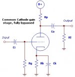
If you look at the diagram, take Ck off, and the electron flow from ground to B+ is fairly linear, steady, and the response character to differing waveforms, the transient response is pretty linear, or similar over a broad frequency range.
When you attach Ck, then you are introducing the response character of the cap to the circuit, and since varying voltage to the cathode, then the cap is controlling the tube, making it follow it's response character.
If you have say three stages in a row, the response character of each cap is not equal, and since the voltage varyance is not equal across each cap, then from in to out, you will add in the varying responses to signal change, and waveform of the caps.
Adding a small amount, 47 ohm to 330 ohm, in between the cathode, and Rk/Ck, that small amount of resistance acts like a shock absorber and smooths transient response out, allows the tube to push back also.
I tried, in two stage line preamps with balance and volume controls, 12ax7 1st stage, 12au7 2nd stage, two 12au7, 5963, 6fq7, 6gu7, 6sn7, four #37/76, then two 6fm7, giving the biggest smooth tone gigantic soundstage of all.
No bypass caps, flat response down to 20-25 Hz, excellent square wave response, super quiet, no system i ever built had any noise at all, and very clear soundstage.
I dealt with the evil in and out caps overshoot, by using about a 15K in resistor, and a 22K between the in cap and the grid, two "shock absorbers" on either side of the cap, pushing back to damping transient overshoot.
I also put a 5.6K between the plate and the out cap, and 12K between the pot cap and it's load to do same.
If you use carbon resistors, they have a slow response time, and some of the audiophile resistors have musical response character.
Your circuit, is the response character of the tubes, caps and resistors.
The big new deal in the late 70's was to do transient response tests. I have a old Heath switcher, that switches between two inputs. Then I could feed a signal that changed from sine to square, same frequency, to any circuit or amp.
If the circuit or amp was fast, then the wavform simply changed instantly with no overshoot, or wiggling. If it was slow, then each time the waveform changed, there would be a "wiggle" before becoming steady.
I had twelve of the best liked stereo power amps of the time in the shop, including a Marantz 250 or 260?? can't remember, and a amp from a small company that I liked the highs on the best.
I tested all the amps with basic square wave, and sign wave frequency response, and all pretty close to the same.
The two amps, the Marantz, and the one I liked, whih had the best clarity, best smooth clean highs, had the best transient response.
If you tested the triode stage with a say 100Mfd bypass cap, it would show lousy transient response, due the the cap.
I just replaced caps in some Threshold gear with ELNA cerafine caps, and they are much tighter, sound Fab, but nothing is as fast and linear as pure resistor and tube.
I re-built two Mac C-4 preamps, for stereo, about two years into building line preamps, for a customer. I left the line out triod unbypassed. We did a listen test, sounded smooth, quiet. I connected bypass caps, and then harsh, hiss came back, so I took them off, and never used them again.
Hi
I have been working with our 3-D film company emergiencies so I lost a week or would have replied sooner.
The "Puddle Effect" is when you have a pool of electrons, like water in a lake, and for various reasons, the puddle of electrons and the surface of the lake is not steady.
Electron flow through a triode/tube can vary due to unsteady B+, filament, the filament in the tube, conductivity of the cathode and plate, unsteady grid support and more.
Then if you have a basic tube gain stage and add a cap across the cathode, a pool of electrons is at the ground end, and they flow from negative, ground to positive, the plate, or B+.
Since everything is tied to ground, including the AC, ground itself can be unsteady, and that transfers to the negative side of any cap tied to ground, then to the other end to the cathode, making the circuit unsteady.
Capacitors themselves can be unsteady depending on dialectrics, quality, age etc., or just the fact that a pile of electrons is not steady also.
I use Mr. scope, and Mr. oscillator, and also two old tube signal tracers to "Listen" to circuits, and also that big meter on my trusty Simpson 260.
Some time ago, I was re-building a Fender amp, can't remember what model after doing so many, and I was tuning up the two 6l6 output stage. I was measuring the voltage at the plates, with my trusty Simpson 260, with it's large meter, and I noticed that the voltage drop across the output transformer winding was wiggling. This showed me that the output stage, typical in guitar amps, was unstable.
I inserted a 33 Ohm resistor in series with the cathode of each 6l6, and the small bit of negative feedback at the cathodes made the tubes rock stable. The amp also sounded warmer, as the dynamic response of the tubes was slowed down a bit.
I have used the trick of inserting from 12 to 75 ohms in between cathod and ground in many guitar amp modding jobs, to get a much warmer sound, and quieter.
If you look at the diagram, take Ck off, and the electron flow from ground to B+ is fairly linear, steady, and the response character to differing waveforms, the transient response is pretty linear, or similar over a broad frequency range.
When you attach Ck, then you are introducing the response character of the cap to the circuit, and since varying voltage to the cathode, then the cap is controlling the tube, making it follow it's response character.
If you have say three stages in a row, the response character of each cap is not equal, and since the voltage varyance is not equal across each cap, then from in to out, you will add in the varying responses to signal change, and waveform of the caps.
Adding a small amount, 47 ohm to 330 ohm, in between the cathode, and Rk/Ck, that small amount of resistance acts like a shock absorber and smooths transient response out, allows the tube to push back also.
I tried, in two stage line preamps with balance and volume controls, 12ax7 1st stage, 12au7 2nd stage, two 12au7, 5963, 6fq7, 6gu7, 6sn7, four #37/76, then two 6fm7, giving the biggest smooth tone gigantic soundstage of all.
No bypass caps, flat response down to 20-25 Hz, excellent square wave response, super quiet, no system i ever built had any noise at all, and very clear soundstage.
I dealt with the evil in and out caps overshoot, by using about a 15K in resistor, and a 22K between the in cap and the grid, two "shock absorbers" on either side of the cap, pushing back to damping transient overshoot.
I also put a 5.6K between the plate and the out cap, and 12K between the pot cap and it's load to do same.
If you use carbon resistors, they have a slow response time, and some of the audiophile resistors have musical response character.
Your circuit, is the response character of the tubes, caps and resistors.
The big new deal in the late 70's was to do transient response tests. I have a old Heath switcher, that switches between two inputs. Then I could feed a signal that changed from sine to square, same frequency, to any circuit or amp.
If the circuit or amp was fast, then the wavform simply changed instantly with no overshoot, or wiggling. If it was slow, then each time the waveform changed, there would be a "wiggle" before becoming steady.
I had twelve of the best liked stereo power amps of the time in the shop, including a Marantz 250 or 260?? can't remember, and a amp from a small company that I liked the highs on the best.
I tested all the amps with basic square wave, and sign wave frequency response, and all pretty close to the same.
The two amps, the Marantz, and the one I liked, whih had the best clarity, best smooth clean highs, had the best transient response.
If you tested the triode stage with a say 100Mfd bypass cap, it would show lousy transient response, due the the cap.
I just replaced caps in some Threshold gear with ELNA cerafine caps, and they are much tighter, sound Fab, but nothing is as fast and linear as pure resistor and tube.
I re-built two Mac C-4 preamps, for stereo, about two years into building line preamps, for a customer. I left the line out triod unbypassed. We did a listen test, sounded smooth, quiet. I connected bypass caps, and then harsh, hiss came back, so I took them off, and never used them again.
Attachments
Is that like the Fermi sea, only smaller?ElectricMan said:The "Puddle Effect" is when you have a pool of electrons, like water in a lake, and for various reasons, the puddle of electrons and the surface of the lake is not steady.
I fear you may have taken the 'electric wires as water pipes' analogies taught to newbies rather too seriously!
Puddle effect 2
Hi
Sorry for being long winded
I had a electronics class in high school, and the teacher used old Navy films
that showed the actual free electrons flowing through the wires and parts.
I had a shock when taking electronics in college and I one day, realized that the guy next to me, very bright, had no actual idea as to what electron flow was. He could do all the engineering math and more, but no idea what actually
happened with those crazy free electrons.
I can't find any of those films online, but this video is pretty cute, and correct.
Electric current - YouTube
I have books going back to a 1912 Hawkins Electricity dictionary, and love all the older graphics that show the actual physics.
NOTE: The power company is charging you for "Free Electrons" (sorry)
I grew up with Ham radio guys and was around high voltage, big triodes from
around 11 or so. I could not build a audio amp even with help. One day, my dad bought a small Heathkit mono amp, and I managed to build it correct.
Two guys I knew, that sold Ham Radio parts, had a 1950's era and very early,
1920's eary radio museum. They had a working spark transmitter, about 5
kilowatt, Telsa coil et. all. I always wanted to hook up a antenna and see if we could blank out every TV set for about 20 miles!
So, I am being a pest with the electron flow, heh??
I have a friend, Thomas, who runs Thunderbird Studios in Oceanside, analog,
1" tape, two blocks from the beach. He was having noise problems that we
solved by isolating the AC and ground in the studio from the power line.
There are still times when he can't record because two old power lines end by
the studio. His street goes down to the beach where there was a pier.
These old poles have lines that go underground there, and when there is any
lightning, the whole "Ground" on this street is active, so anything connected to ground, the noise comes up from ground, making all the mike lines and console mike preamps noisy.
So, going back to the cap.
A 100Mfd cap is 100Mfd because it can store enough electrons to flow out from negative to positive in a given time. A 10Mfd can store about 1/10th that, a 1mfd, 1/100th that.
So, when you connect a 100mfd cap to the cathode, you are connecting a two plates, foil device, one side with a pile of electrons hooked to ground, the other side, with no electrons to the cathode. The ground is this pool of electrons, that gets bigger with everything else connected to it.
So, then driving AC through that cap, is like having a speaker above a pond,
nice flat water, and driving audio down towards bottom, or actually maybe up.
If the water is such, maybe dense enough, then the audio will flow through the water without too much change and come out clear at the other side.
If the water is not dense, or very active, then many responding vibrations will
add distortions to the audio waves.
So the response character to electron flow of a cap will modulate the cathode and drive the tube, making the tube respond to the characer of the cap, adding it's artifacts to the signal.
If you look at older "Vintage" audio circuits, they used smaller coupling caps
and higher impedance loads, .022mfd into 500k to 1 meg, maybe .22mfd into
220 to 330K, for economy, and sometimes the need for smaller caps in tight
spaces, but also, smaller caps have faster response character, than bigger values like 2.2Mfd into a 50K load.
I build line stages with1 to 2 mfd Paper Oil in caps, and 4 to 8Mfd PIO out caps, as you do get a much bigger low end dynamic running low impedance, but these are PIO or metal poly caps, not electroylitic caps.
I use two different valies on either side of the in/out caps, because the grid of
the tube is much higher impedance. The plate is lower impedance than the load on the other side, so current response character on either side of the cap is different, then different value resistors.
I do not do more than sketching out a design first, untill I am pretty sure of what it should be, and then I build it. I use the customer's ears, and actual live performance as my guide, no CAD stuff.
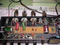
I built about 22 of these transistor stereo mike preamps, DI's, EQ's and more all without any software, just what I learned by build and test, and I have zero returns, almost all is being used constantly.
I also built a small number of these vintage preamps, all used constantly, never and problems, five-pin tubes really great sound, no software, just build and test, and let the studios tell me what.
I worked on Marshall 200 watt, Plush 300 Watt, Hiwatt, Sound City, Fender et. all in the 1970's so around HV and big tubes from early on.
I go by the old tube manuals I have and vintage circuit design also.
Hi
Sorry for being long winded
I had a electronics class in high school, and the teacher used old Navy films
that showed the actual free electrons flowing through the wires and parts.
I had a shock when taking electronics in college and I one day, realized that the guy next to me, very bright, had no actual idea as to what electron flow was. He could do all the engineering math and more, but no idea what actually
happened with those crazy free electrons.
I can't find any of those films online, but this video is pretty cute, and correct.
Electric current - YouTube
I have books going back to a 1912 Hawkins Electricity dictionary, and love all the older graphics that show the actual physics.
NOTE: The power company is charging you for "Free Electrons" (sorry)
I grew up with Ham radio guys and was around high voltage, big triodes from
around 11 or so. I could not build a audio amp even with help. One day, my dad bought a small Heathkit mono amp, and I managed to build it correct.
Two guys I knew, that sold Ham Radio parts, had a 1950's era and very early,
1920's eary radio museum. They had a working spark transmitter, about 5
kilowatt, Telsa coil et. all. I always wanted to hook up a antenna and see if we could blank out every TV set for about 20 miles!
So, I am being a pest with the electron flow, heh??
I have a friend, Thomas, who runs Thunderbird Studios in Oceanside, analog,
1" tape, two blocks from the beach. He was having noise problems that we
solved by isolating the AC and ground in the studio from the power line.
There are still times when he can't record because two old power lines end by
the studio. His street goes down to the beach where there was a pier.
These old poles have lines that go underground there, and when there is any
lightning, the whole "Ground" on this street is active, so anything connected to ground, the noise comes up from ground, making all the mike lines and console mike preamps noisy.
So, going back to the cap.
A 100Mfd cap is 100Mfd because it can store enough electrons to flow out from negative to positive in a given time. A 10Mfd can store about 1/10th that, a 1mfd, 1/100th that.
So, when you connect a 100mfd cap to the cathode, you are connecting a two plates, foil device, one side with a pile of electrons hooked to ground, the other side, with no electrons to the cathode. The ground is this pool of electrons, that gets bigger with everything else connected to it.
So, then driving AC through that cap, is like having a speaker above a pond,
nice flat water, and driving audio down towards bottom, or actually maybe up.
If the water is such, maybe dense enough, then the audio will flow through the water without too much change and come out clear at the other side.
If the water is not dense, or very active, then many responding vibrations will
add distortions to the audio waves.
So the response character to electron flow of a cap will modulate the cathode and drive the tube, making the tube respond to the characer of the cap, adding it's artifacts to the signal.
If you look at older "Vintage" audio circuits, they used smaller coupling caps
and higher impedance loads, .022mfd into 500k to 1 meg, maybe .22mfd into
220 to 330K, for economy, and sometimes the need for smaller caps in tight
spaces, but also, smaller caps have faster response character, than bigger values like 2.2Mfd into a 50K load.
I build line stages with1 to 2 mfd Paper Oil in caps, and 4 to 8Mfd PIO out caps, as you do get a much bigger low end dynamic running low impedance, but these are PIO or metal poly caps, not electroylitic caps.
I use two different valies on either side of the in/out caps, because the grid of
the tube is much higher impedance. The plate is lower impedance than the load on the other side, so current response character on either side of the cap is different, then different value resistors.
I do not do more than sketching out a design first, untill I am pretty sure of what it should be, and then I build it. I use the customer's ears, and actual live performance as my guide, no CAD stuff.
I built about 22 of these transistor stereo mike preamps, DI's, EQ's and more all without any software, just what I learned by build and test, and I have zero returns, almost all is being used constantly.
I also built a small number of these vintage preamps, all used constantly, never and problems, five-pin tubes really great sound, no software, just build and test, and let the studios tell me what.
I worked on Marshall 200 watt, Plush 300 Watt, Hiwatt, Sound City, Fender et. all in the 1970's so around HV and big tubes from early on.
I go by the old tube manuals I have and vintage circuit design also.
Attachments

As I said, 'water in pipes' analogies are used for teaching complete newbies. Continuing with that analogy has led you astray. Electrons don't behave like water.
It would take me too long to go through your post line by line and correct your misunderstandings and quaint analogies. I suggest you read a good book: Horowitz and Hill is the usual one we suggest.
It would take me too long to go through your post line by line and correct your misunderstandings and quaint analogies. I suggest you read a good book: Horowitz and Hill is the usual one we suggest.
- Status
- This old topic is closed. If you want to reopen this topic, contact a moderator using the "Report Post" button.
- Home
- Amplifiers
- Tubes / Valves
- need help to fix the "hiss" on my tube preamp