I've been playing with the autobias circuit that Anatoliy used in one of his designs. I'm new on autobias, so please be patient with me ")
I'm looking at improving my current 45SE which is running with fixed bias. Sound is superb, but would like to avoid the hassle of adjusting bias, etc.
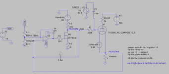
The attached design seems to simulate ok. Clearly C1 seems to improve frequency response but not sure how C1 and C4 should play together here to optimise the performance of this circuit at low frequency...
EDIT: driver and 45 load are simplified here only to show connections with servo circuit.
I've seen also that Morgan Jones proposed a more complicated design, is it worth investigating that path or will this simple design be sufficient?
Thanks
Ale
I'm looking at improving my current 45SE which is running with fixed bias. Sound is superb, but would like to avoid the hassle of adjusting bias, etc.
The attached design seems to simulate ok. Clearly C1 seems to improve frequency response but not sure how C1 and C4 should play together here to optimise the performance of this circuit at low frequency...
EDIT: driver and 45 load are simplified here only to show connections with servo circuit.
I've seen also that Morgan Jones proposed a more complicated design, is it worth investigating that path or will this simple design be sufficient?
Thanks
Ale
Attachments
Last edited:
Hi Ale,
the simplest method of autobias is the good old cathode resistor. After trying different bias methods years ago. That is what I have settled for in most cases. Coupled with the ultrapath connection from B+ to cathode this is hard to beat in terms of sound quality, simplicity and reliability.
Cathode bias lets the tube settle itself in the right operating point. I don't want to discourage you from other bias methods, but you should at least try it as well.
Best regards
Thomas
- Status
- This old topic is closed. If you want to reopen this topic, contact a moderator using the "Report Post" button.