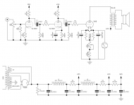
I planning build something similar to this amplifier 300B Mk2 Triode Amplifier, but with some small changes.
I have capacitors for this amp. For one chanel:
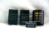
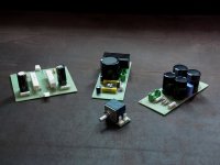
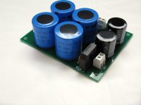
- for power supply 1x20uF Mundorf TubeCap, 4x47uF Mundrof TubeCap, 1x30uF Mundorf TubeCap
- for amplifier 1x47uF Mundorf MCap, 1x100uf Mundorf MCap, 1x Mundorf Supereme Silver OIL 0.22uf.
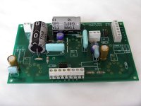
Power transformers, chocke and output transforemer, I have form Polish manufacturer - EDIS (Ogonowski).
As volume potentiometer I use Khozmo Attenuator - High Quality Audio & Industrial Attenuators")
Now I looking for resistor, especially for cathode resistor. I found something like this TDO japan made resistors, but I can't found any opinion abut this resistors. Maybe some of you had to do with them?
I have capacitors for this amp. For one chanel:
- for power supply 1x20uF Mundorf TubeCap, 4x47uF Mundrof TubeCap, 1x30uF Mundorf TubeCap
- for amplifier 1x47uF Mundorf MCap, 1x100uf Mundorf MCap, 1x Mundorf Supereme Silver OIL 0.22uf.
Power transformers, chocke and output transforemer, I have form Polish manufacturer - EDIS (Ogonowski).
As volume potentiometer I use Khozmo Attenuator - High Quality Audio & Industrial Attenuators
Now I looking for resistor, especially for cathode resistor. I found something like this TDO japan made resistors, but I can't found any opinion abut this resistors. Maybe some of you had to do with them?
Attachments
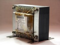
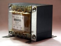
I already have the output transformer - as in the description and the fotakch above;-) I have OT on EI96 core (0.3 mm).
I think it's priced at 10€ for resistor in not so much at the amount that I gave for capacitors.
Other options for cathode resistor is 2 x Mills MRA-12 1,8k in parallel. But this give me 900ohm, not 880 ;-)
I think it's priced at 10€ for resistor in not so much at the amount that I gave for capacitors.
Other options for cathode resistor is 2 x Mills MRA-12 1,8k in parallel. But this give me 900ohm, not 880 ;-)
Why spend 10€ on a cathode resistor ? EDIS, the transformer manufacturer, has very good C-Cores. This would be a better alternative to spend the money.
+++ I Agree...
But I already have the output transformers;-) At the core of EI96, 0.3mm blade.
Other option for cathode resistor is 2 x Mills MRA-12 1,8k in parallel.
And I have one more question. I have two power transformer. Each have 380-0-380V 200mA, as in the original Angela project - 300B Mk1 Tube Amplifier. But this 200mA is not too much for one chanel?
Other option for cathode resistor is 2 x Mills MRA-12 1,8k in parallel.
And I have one more question. I have two power transformer. Each have 380-0-380V 200mA, as in the original Angela project - 300B Mk1 Tube Amplifier. But this 200mA is not too much for one chanel?
It takes much more that expensive parts to make a great amplifier. I would start with a good schematic. The most expensive capacitor in the universe will still sound veiled compared to NO capacitor; you need to direct couple the driver to the output tube.
You can't just take someone's schematic and expect to construct the exact same thing. There is always testing and experimenting to achieve the best sound. For instance you are worried about the power transformer. Yes it might provide more voltage than you need. That might require a cathode resistor of 900 ohms. You won't know until you build the unit and then test it and refine it.
If I were building this amp, instead of buying one $15 resistor I would buy a bunch of modestly priced resistors say 750, 800, 880, 900, etc. to "dial in" the operating point of the output tube. This is an iterative process. Even a recipe for chocolate cake will require some experimentation to get it to your own "taste".
Yes, you're right. I remember how I built small SE amplifier on the EL84. I chose value of the cathode resistor soldered it to the wires
It can actually do the same here, first I solder cheap resistors on the wires and, as already establishes the value of this can I change it to something better.
But I am still worried about the winding 380-0-380 - it seems to me that a lot of 200mA is too much for one channel of the 6SN7 + 300B.
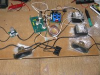
And one more thing I still like my EL84 SE, but I want to have my own 300B;-) I buy some expensvie parts, because somehow seem more suited to audiophile - 300B;-)
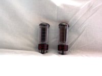
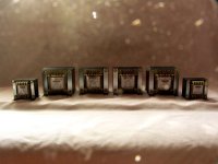
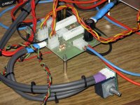
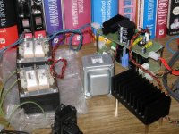
I add some old photos of my EL84, and my OTl on 6as7g ;-)
It can actually do the same here, first I solder cheap resistors on the wires and, as already establishes the value of this can I change it to something better.
But I am still worried about the winding 380-0-380 - it seems to me that a lot of 200mA is too much for one channel of the 6SN7 + 300B.
And one more thing
I still like my EL84 SE, but I want to have my own 300B;-) I buy some expensvie parts, because somehow seem more suited to audiophile - 300B;-) I add some old photos of my EL84, and my OTl on 6as7g ;-)
Attachments
Last edited:
But I am still worried about the winding 380-0-380 - it seems to me that a lot of 200mA is too much for one channel of the 6SN7 + 300B.
Trannies are wound to a voltage at a certain current.
the numbers don't add up
Yes, the power transformer will probably provide more voltage than the schematic calls for, but it will run cool and unstressed. So in the end that is a good thing. This means that you will need to be prepared to re-engineer the voltages on the voltage amp, driver and output tube. Since the front end is direct coupled you will need to juggle different values of resistors to get the thing working properly.
I should mention in relation to this that the voltages and currents listed on the schematic don't add up anyway, so quite a bit of testing and experimenting will be required to make it work properly. A quick for instance: we know that the first tube is drawing 3mA (3V/1k ohms) exactly; if we multiply 3mA by the plate resistor we get 204 volts. If we add that to the plate voltage we get 296V. The schematic lists B+ for this stage at 320V so we have a big error right there. The exact same problem arises with the second stage: the numbers don't add up.
So instead of worrying about expensive parts you should be building the circuit and experimenting with component values to determine exactly which parts you will need. This amplifier can't work as shown on the schematic, but the circuit topology will definitely work once you get all the proper voltages and component values worked out.
The text with the schematic states pretty clearly that the voltages provided are only approximate, but I'm wondering what sort of multi-meter was used to measure them as they do not jibe..
They aren't extremely critical although I will say that available driver headroom is not much. One worthwhile improvement might be to consider a choke load (plate choke) on the second stage in lieu of the resistor - noting that some adjustment to plate voltage to that stage will be required, this will give you headroom to spare and a significant improvement in linearity as well.
They aren't extremely critical although I will say that available driver headroom is not much. One worthwhile improvement might be to consider a choke load (plate choke) on the second stage in lieu of the resistor - noting that some adjustment to plate voltage to that stage will be required, this will give you headroom to spare and a significant improvement in linearity as well.
It takes much more that expensive parts to make a great amplifier. I would start with a good schematic. The most expensive capacitor in the universe will still sound veiled compared to NO capacitor; you need to direct couple the driver to the output tube.
I couldn't agree more. The schematic linked to in Post #1 will suffer from blocking distortions at high output powers (i.e. on transients). One solution to that is to directly couple the driver to the 300B. Another solution is to use a cathode or source follower to drive the 300B. You can cap couple into the cathode/source follower if you wish. See Tubelab's PowerDrive for an example of this.
I buy some expensvie parts, because somehow seem more suited to audiophile - 300B;-)
Solid silver wire, paper-in-oil capacitors, and certified organic myrtlewood speaker cable stands may turn your design into an "Audiophile Grade" design, but they won't do anything to fix any design flaws in your circuit. They won't make a poor design sound better than a good design either.
But hey.... It's your money and the components you have look quite suitable for a good amp build.
I would suggest using the schematic you list as a starting point for experimentation. Use the regular 10-cent Yaego resistors that you can get anywhere. Try a couple of different circuit topologies. Once you find something that you like, then you can splurge on boutique components if that suits your fancy.
Just my opinion... I've spent the past 2+ years perfecting my 300B design. I've gone through at least five different circuit topologies and am now finally at the point where I'm satisfied with the sound. Which reminds me... I should probably write up the design description and post it here.
Driving a 300B is quite tricky. The driver needs to provide 150 Vpp of voltage swing at low distortion and relatively high slew rate. Hence, the key to driving a 300B well is to design the driver such that it can supply a bit of grid current to the 300B. Just a few mA...
~Tom
The text with the schematic states pretty clearly that the voltages provided are only approximate
The author states, "The voltages shown are only a guide and will vary with different tube line up and also mains supply variations, which makes these impossible to be exact about [sic]."
I fully agree that the actual voltages will vary dependent on a multitude of factors, but what I think is wrong is to publish a schematic that does not work on paper and then state that it is "impossible to be exact". It is not impossible to draw up a technically accurate schematic. I expect the schematic to be technically accurate and that if I draw up load lines for the tubes in the schematic, the operating point should fall onto the load lines, and if there are currents through passive devices the proper voltage drop should be expressed on the schematic.
Maybe I am being too critical, but I would be embarrassed publish a schematic on line that was not technically accurate. In this case it appears that the OP thinks that he can just assemble this amplifier according to the schematic and the voltages will work out. They will not and it is not a result of "different tube line up and also mains supply variations" but a schematic that is just plain wrong.
For now I have 4 chockes in PSU ;-) 2 for each channel. For now, I don't want 2 more chokes. Maybe in future, who knows.
Any way, in weekend I must recalculate and check schematic. And must found same cheap 20-30W resistors for test.
At the beginning I planned to build an amplifier based on generally known pattern Angela http://www.tubesrit.com/audio/albums/userpics/10001/JE_Labs_300B_Schematic.gif (300B Mk1 Tube Amplifier), but with more extensive PSU (larger capacity and two chokes, and stabilized 300b's heater). I might go back to this idea.
From what I know JE Labs 300B has been successfully built by many people.
Yes, I know it's stupidity. As you've seen on the photos, my previous tube amps are composed of "normal" part. Here is such a stupid fad;-) And there is no denying that these audiophile gadgets are just pretty;-)
And one more thing - I have not found other normal-sized capacitors 47uF/600V. Only large oil jars ..
Any way, in weekend I must recalculate and check schematic. And must found same cheap 20-30W resistors for test.
At the beginning I planned to build an amplifier based on generally known pattern Angela http://www.tubesrit.com/audio/albums/userpics/10001/JE_Labs_300B_Schematic.gif (300B Mk1 Tube Amplifier), but with more extensive PSU (larger capacity and two chokes, and stabilized 300b's heater). I might go back to this idea.
From what I know JE Labs 300B has been successfully built by many people.
Solid silver wire, paper-in-oil capacitors, and certified organic myrtlewood speaker cable stands may turn your design into an "Audiophile Grade" design, but they won't do anything to fix any design flaws in your circuit. They won't make a poor design sound better than a good design either.
But hey.... It's your money and the components you have look quite suitable for a good amp build.
Yes, I know it's stupidity. As you've seen on the photos, my previous tube amps are composed of "normal" part. Here is such a stupid fad;-) And there is no denying that these audiophile gadgets are just pretty;-)
And one more thing - I have not found other normal-sized capacitors 47uF/600V. Only large oil jars ..
Last edited:
For now I have 4 chockes in PSU ;-) 2 for each channel. For now, I don't want 2 more chokes.
I'd scrap the chokes and use a voltage regulator. See my website for detail.
Any way, in weekend I must recalculate and check schematic. And must found same cheap 20-30W resistors for test.
I don't see a reason for the 50 W cathode resistor. That value must be because that's what the author had on hand. I've never dissipated more than a few watt (maybe as much as 5 W) in a 300B cathode resistor. But then I usually don't use cathode feedback either.
Of course, the power dissipated will come out of your calculations. I'd go with a resistor that can handle 3~4x the dissipated power.
I have not found other normal-sized capacitors 47uF/600V. Only large oil jars ..
Solen has 47 uF, 630 V polypropylene. I have four of them. They're rock solid! I measured the ESR of them on an impedance analyzer. They come in around 5 mOhm. I actually won't be using them so if you're interested in a trade, toss me a PM.
~Tom
Solen has 47 uF, 630 V polypropylene. I have four of them. They're rock solid! I measured the ESR of them on an impedance analyzer. They come in around 5 mOhm. I actually won't be using them so if you're interested in a trade, toss me a PM.
Thanks for this offer but I but I already have 8 pieces Mundorf 47uF/600V Tube Cap (http://www.mundorf.com/english 1.1/Broschuere Einzelseiten/MTube Cap.pdf). These are also the polypropylene, the price of what I see similar to this Solen.
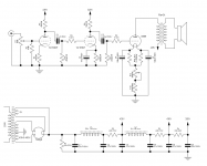
And probably the final version. The changes have helped me make friends with one of Polish forums As you can see, this is a technical forum, not audiophile;-) Changed include operating points for each grade, as well as the degree of coupling between the input and driver stage.
As you can see, this is a technical forum, not audiophile;-) Changed include operating points for each grade, as well as the degree of coupling between the input and driver stage.Attachments
I planning build something similar to this amplifier 300B Mk2 Triode Amplifier, but with some small changes.
I have capacitors for this amp. For one chanel:
- for power supply 1x20uF Mundorf TubeCap, 4x47uF Mundrof TubeCap, 1x30uF Mundorf TubeCap
- for amplifier 1x47uF Mundorf MCap, 1x100uf Mundorf MCap, 1x Mundorf Supereme Silver OIL 0.22uf.
Power transformers, chocke and output transforemer, I have form Polish manufacturer - EDIS (Ogonowski).
As volume potentiometer I use Khozmo Attenuator - High Quality Audio & Industrial Attenuators
Now I looking for resistor, especially for cathode resistor. I found something like this TDO japan made resistors, but I can't found any opinion abut this resistors. Maybe some of you had to do with them?
I put 10 pcs of 2w RMG resistors (10K ohm each) in parallel on the 300B cathode. I made a lot of comparison and believed that is the best so far so me...I can also adjust the valve of the resistance by reduce or add 1 or 2 resistors.
May be an option for you...
Hi!
Why did you make the cathode resistor adjustable? Cathode bias is meant to be automatic and the tube will find the most healthy op point by itself.
Why the 2W gridstoppers? 0.5W would be sufficient and are smaller. I never found the need to use gridstoppers on tubes like 6SN7 and 300B. These tubes are not prone to oscillation IME. If you insist to use them, then also use one at the input triode for consistency.
This design will have a lot of gain. If you use 2V sources the volume control pot will only have a limited useful range. If your sources have lover leverl, it is fine.
Bets regards
Thomas
- Status
- This old topic is closed. If you want to reopen this topic, contact a moderator using the "Report Post" button.
- Home
- Amplifiers
- Tubes / Valves
- SE on 300B