Hi,
Experiencing very good results and sound from a preamplifier based upon John Broskies CCDA concept using 6C4 miniature triodes, I had an idea doing the same using some DHT's which are normally not quite handy in a preamplifier.
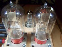
I have some Siemens Ba Post triodes on stash and I always wanted to build a preamplifier using them, but the high plate-resistance kept these in the drawer.. Looking at it's specs, it sits at 3mA on 220Volt plate voltage biased at -6Volts. Searching some tube data I found that the ECC40 has an identical point... The idea was to use the Ba as input tube directly coupled to the ECC40 similar as John's CCDA design.
Datasheets show that the Ba can be loaded with 25K, I ended up with a 81K plate load since a 39K resulted in limited bandwidth (<22Khz). 81K because of the power transformer I had at hand. A bit high voltage for a preamplifier, but hey, what the heck..
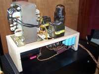
So a mock-up was quickly realized and the preamp is playing now for some hours with very good results.. Tubes settle in just as expected and it has an overall gain of about 18dB..
Because of the dissimilar triodes being used, it will not be an exact CCDA design, but it is close..
Please comment..
Rob
Experiencing very good results and sound from a preamplifier based upon John Broskies CCDA concept using 6C4 miniature triodes, I had an idea doing the same using some DHT's which are normally not quite handy in a preamplifier.
I have some Siemens Ba Post triodes on stash and I always wanted to build a preamplifier using them, but the high plate-resistance kept these in the drawer.. Looking at it's specs, it sits at 3mA on 220Volt plate voltage biased at -6Volts. Searching some tube data I found that the ECC40 has an identical point... The idea was to use the Ba as input tube directly coupled to the ECC40 similar as John's CCDA design.
Datasheets show that the Ba can be loaded with 25K, I ended up with a 81K plate load since a 39K resulted in limited bandwidth (<22Khz). 81K because of the power transformer I had at hand. A bit high voltage for a preamplifier, but hey, what the heck..
So a mock-up was quickly realized and the preamp is playing now for some hours with very good results.. Tubes settle in just as expected and it has an overall gain of about 18dB..
Because of the dissimilar triodes being used, it will not be an exact CCDA design, but it is close..
Please comment..
Rob
Attachments
Actually a CCDA requires not only equal mu but also equal transconductance at the operating point chosen. When the triodes are the same, this is easy to do since it is relatively easy to chose the same exact operating point by biasing the triodes to 1/2 B+ and running the same current through them (i.e. use anode resistor of the first as cathode of the second). Using dissimilar triodes you might well find two that have a DC operating point where the rest of the parameters are the same but it will be very difficult to set it all up and get optimal results.
However, you might still be able to exploit one particular CCDA point and that is the absence of a cathode bypass for the first tube, even with dissimilar triodes, by passing only part of the cathode current of the second tube through the cathode resistor of the first one. In general you want your second tube to be high-current, high pm (in order to get low output resistance and drive ability), so this can work with a low current high Ra tube as the first one. However, you cannot get power supply current cancellation as for that, both tubes need to operate at the same current.
However, you might still be able to exploit one particular CCDA point and that is the absence of a cathode bypass for the first tube, even with dissimilar triodes, by passing only part of the cathode current of the second tube through the cathode resistor of the first one. In general you want your second tube to be high-current, high pm (in order to get low output resistance and drive ability), so this can work with a low current high Ra tube as the first one. However, you cannot get power supply current cancellation as for that, both tubes need to operate at the same current.
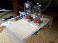
I always enjoy the sight of your woodwork. Have you visited the A'dam Fijnhout Centrale in the Amsterdam Docks? Good source for exotic wood and veneers.
What's the mu of the Ba, 8-ish?
I'd like to give the 27 a try and calculated a 24K load to a 240V supply. See graphic.
Would it be possible you guess to power four 27s in series (perhaps with the help of a 1.75A current limiter)?
What's the mu of the Ba, 8-ish?
I'd like to give the 27 a try and calculated a 24K load to a 240V supply. See graphic.
Would it be possible you guess to power four 27s in series (perhaps with the help of a 1.75A current limiter)?
An externally hosted image should be here but it was not working when we last tested it.
An externally hosted image should be here but it was not working when we last tested it.
Last edited:
@ ilimzn.Actually a CCDA requires not only equal mu but equal transconductance
Thanks for that.
I completely agree on your remark about the possible omission of the bypass cap on the cathode resistor. I did some listening tests and found out that the omission of the cap is worthwhile doing so but sharing the cathode resistor made the sound more controlled, holographic..
Indeed, when aiming for low output impedance you want a high gm tube at the end.. However, I took the easy way by choosing this' ECC40 operating point, simplifying maths..
Rob
Would it be possible you guess to power four 27s in series
Yes. I have done that several times. Works fine. However when putting the filaments in series you strongly rely on filament tolerances wrt resistance.. I remember some '27 in series, one at 2.8volts and the other one at 2.2Volts..
Please take admissible heater to cathode voltage into account (I could not find it in datasheets, but kept it within 50Volts).
Rob
@ ilimzn.
Thanks for that.
I completely agree on your remark about the possible omission of the bypass cap on the cathode resistor. I did some listening tests and found out that the omission of the cap is worthwhile doing so but sharing the cathode resistor made the sound more controlled, holographic..
Indeed, when aiming for low output impedance you want a high gm tube at the end.. However, I took the easy way by choosing this' ECC40 operating point, simplifying maths..
Rob
First of all, congratulations for you great mockup skills!
It is an nonC CDA
, because of the very different characteristics of the 2 stages, but I believe that part of the "holographic " effect is exactly because of that. Broskie somewhere explains that this combination produces a slight positive feedback (ie expander) effect. So this is a fortunate result, cause most of the recordings and radio today are way too much compressed.Not to mention the Siemens valves look glorious!
Very true, but in this case we have two dissimilar triodes with the same load resistor.
True, but the CF will have nearly unity gain (presumably), so an equal load resistance is pretty close to the optimum for constant current draw.
- Status
- This old topic is closed. If you want to reopen this topic, contact a moderator using the "Report Post" button.
- Home
- Amplifiers
- Tubes / Valves
- CCDA dissimilar triode preamp