Hi, now it can be told.... ;D
the inspiration for building this amp came from this page: 6C33C-B SE Verstaerker von Juergen Buschmann
as i am one who is not a true copycat in the strictest sense, i made some deviations from the original design, first, i will use fixed biasing, fuses are installed to limit current should the 6C33 tubes decide to run-away, i am confident it will not happen, i did a prior burnin-in of the tubes as per recommendations of the fellows at diy-audio....second is the use of diodes for biasing the cathodes of the 6P15P voltage amp tube, my experience with Broskie's CCDA preamps using diode biasing has been very encouraging that i only use resistor/capacitor cathode bias combo in my guitar amps exclusively....and i am not turning back on that....
so, this is to document construction of the Russian 6C33C SET amp.
It starts with building a set of power traffos and common mode chokes and a pair of OPT's or output transformers capable of about 10watts into 8ohm loads....
i chose a core with center leg of 1.5 inches stacked to 2 inches, the traffo is butt joint with a suitable gapping material of about 0.5mm. the mass of the traffo core was chosen so that core saturation at low frequencies are mitigated. Turns ratio of the OPT is 10, with an rp of 150 ohms, our plate load needs to be 300ohms for maximum power output, but since i am not after maximum power output, i opted for a 600:6ohm OPT, so that with an 8 ohm speaker, the reflected load is 800ohms, very easy for the 6C33 plate, a 4ohm speaker otoh reflects a 400 ohms load to the plate of the 6C33 so that is still greater than 300ohms...
Aanyway real speakers are not constant 8ohms no matter how the manufacter tell us it is so...so it is easy for you to guess why the choice of the 6C33, simply put, design and building of output traffo is easy, the low rp of the 6C33 does not require a high inductance primary, leakage is no problem, inter-leaving is easy, you can opt not to have it...... it's an easy choice if you ask me.....
.....
SET tube amps demand a lot of power for a measly power output, here i am making a power traffo of with a core rating of about about 390watts,if you ask me, i wished this traffo could have been bigger, it will supply a continuos power of a little over 220 watts regardless of whether the amp is playing music or not.....if we were building a classAB amp instead, we could be idling at less than this.
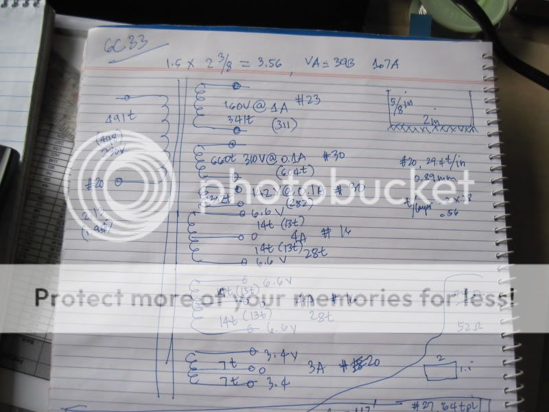
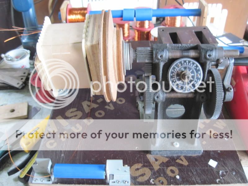
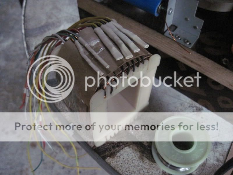
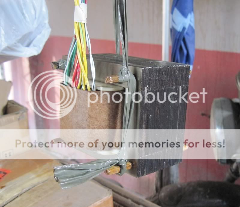
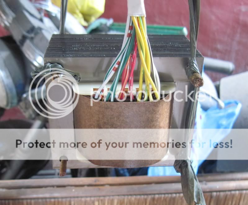
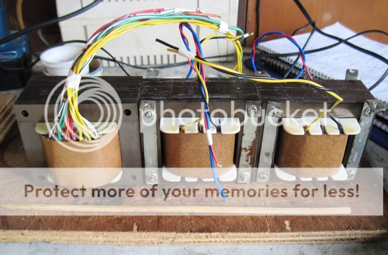
for the power traffo, i used a bobbin for 1.5 inch and 2 3/8 inch stack:
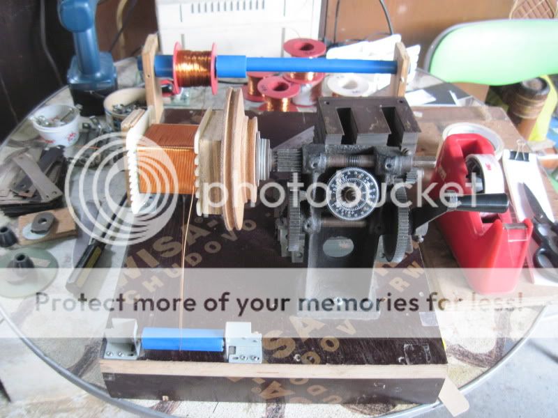
filament winding terminations:
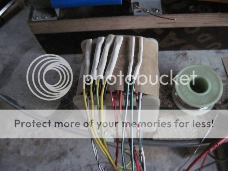
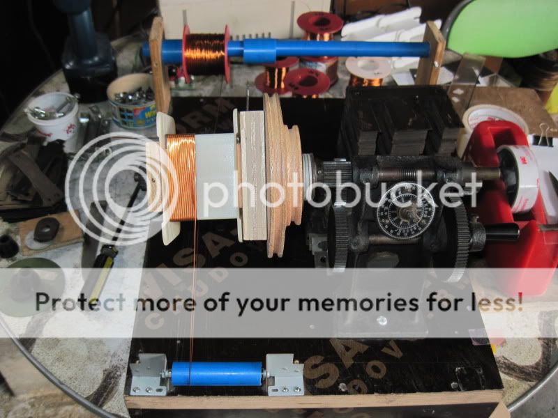
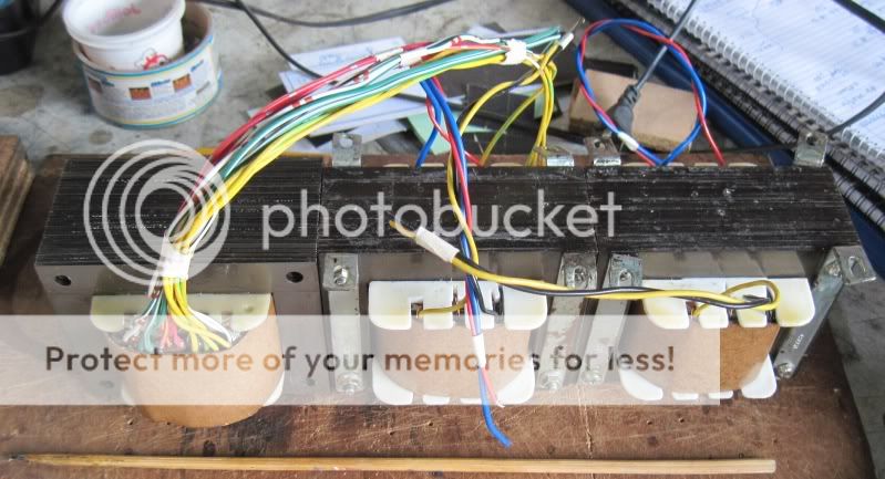
built-up traffo:
bamboo pegs at the 4 mounting holes, this lets the varnish go in between laminates.
here the traffo is hung out to dry for a day or so....
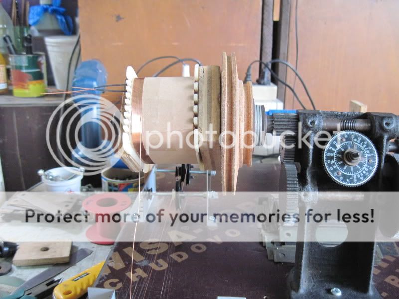
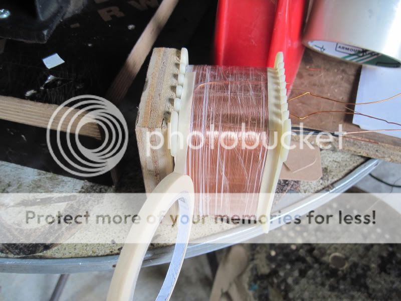
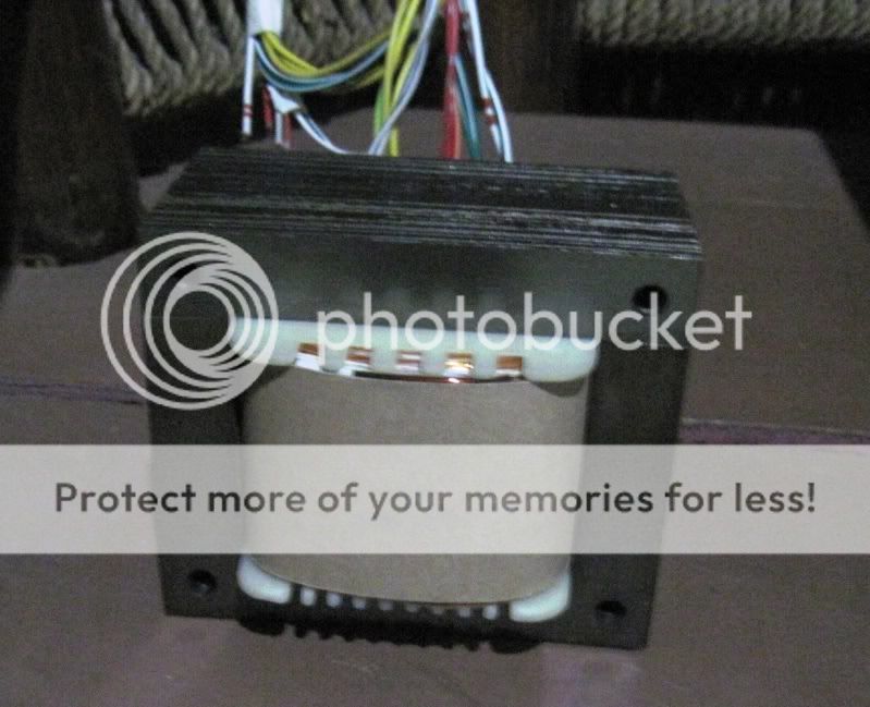
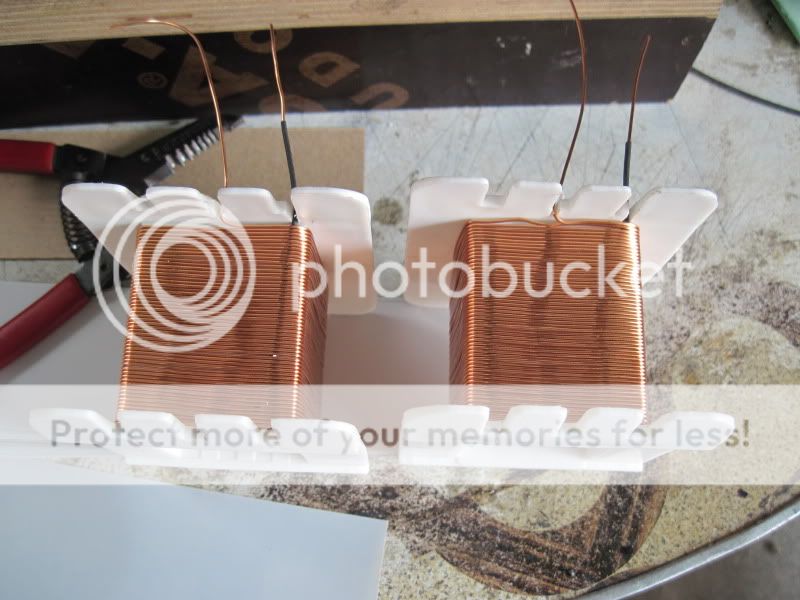
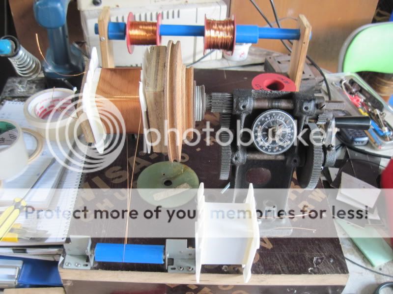
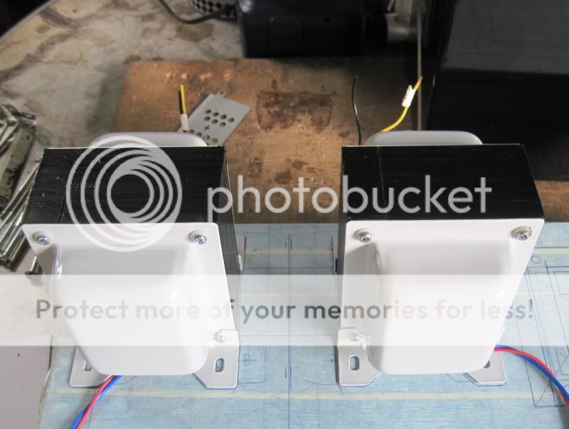
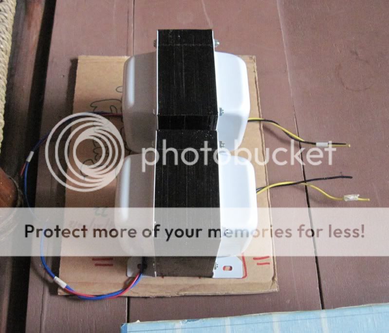
these are the output traffos, core is 1.5 x 2 inches, impedance ratio is 600:6 ohms, so that turns ratio is 10..........
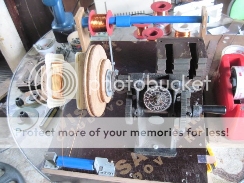
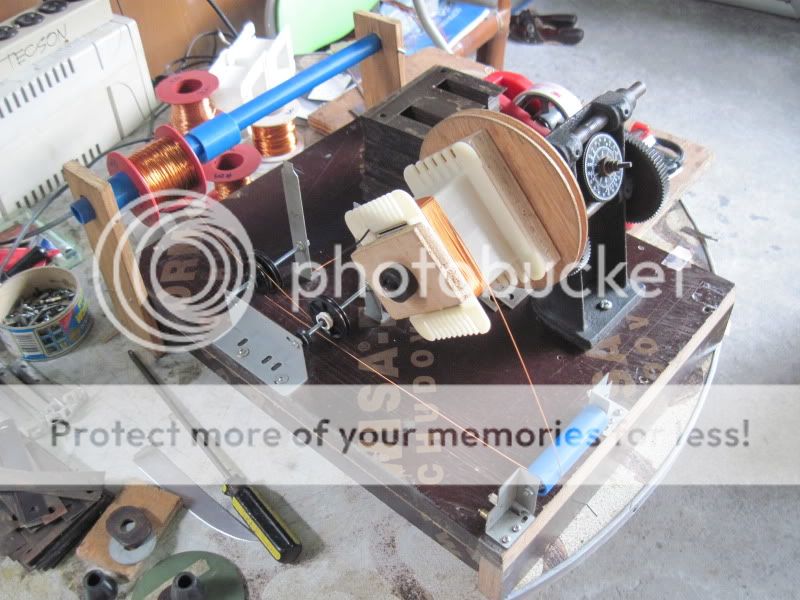
building a pair side by side, one section by one section at a time until the whole buld is completed, ensured that the pair built are identical......
dipping in varnish:
hung out to dry under the sun after dipping in varnish....
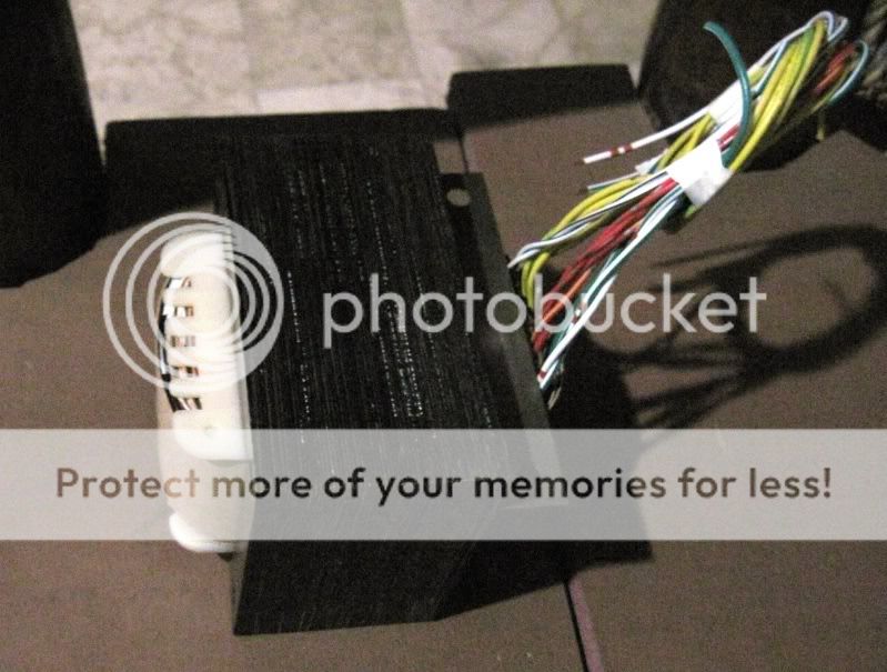
temporary brackets installed on the 2 opts to keep the E's and I's together since they are butt joint with a gapping paper sandwiched in between them...
with endbells installed after painting:
the inspiration for building this amp came from this page: 6C33C-B SE Verstaerker von Juergen Buschmann
as i am one who is not a true copycat in the strictest sense, i made some deviations from the original design, first, i will use fixed biasing, fuses are installed to limit current should the 6C33 tubes decide to run-away, i am confident it will not happen, i did a prior burnin-in of the tubes as per recommendations of the fellows at diy-audio....second is the use of diodes for biasing the cathodes of the 6P15P voltage amp tube, my experience with Broskie's CCDA preamps using diode biasing has been very encouraging that i only use resistor/capacitor cathode bias combo in my guitar amps exclusively....and i am not turning back on that....
so, this is to document construction of the Russian 6C33C SET amp.
It starts with building a set of power traffos and common mode chokes and a pair of OPT's or output transformers capable of about 10watts into 8ohm loads....
i chose a core with center leg of 1.5 inches stacked to 2 inches, the traffo is butt joint with a suitable gapping material of about 0.5mm. the mass of the traffo core was chosen so that core saturation at low frequencies are mitigated. Turns ratio of the OPT is 10, with an rp of 150 ohms, our plate load needs to be 300ohms for maximum power output, but since i am not after maximum power output, i opted for a 600:6ohm OPT, so that with an 8 ohm speaker, the reflected load is 800ohms, very easy for the 6C33 plate, a 4ohm speaker otoh reflects a 400 ohms load to the plate of the 6C33 so that is still greater than 300ohms...
Aanyway real speakers are not constant 8ohms no matter how the manufacter tell us it is so...so it is easy for you to guess why the choice of the 6C33, simply put, design and building of output traffo is easy, the low rp of the 6C33 does not require a high inductance primary, leakage is no problem, inter-leaving is easy, you can opt not to have it...... it's an easy choice if you ask me.....
.....
SET tube amps demand a lot of power for a measly power output, here i am making a power traffo of with a core rating of about about 390watts,if you ask me, i wished this traffo could have been bigger, it will supply a continuos power of a little over 220 watts regardless of whether the amp is playing music or not.....if we were building a classAB amp instead, we could be idling at less than this.
for the power traffo, i used a bobbin for 1.5 inch and 2 3/8 inch stack:
filament winding terminations:
built-up traffo:
bamboo pegs at the 4 mounting holes, this lets the varnish go in between laminates.
here the traffo is hung out to dry for a day or so....
these are the output traffos, core is 1.5 x 2 inches, impedance ratio is 600:6 ohms, so that turns ratio is 10..........
building a pair side by side, one section by one section at a time until the whole buld is completed, ensured that the pair built are identical......
dipping in varnish:
hung out to dry under the sun after dipping in varnish....
temporary brackets installed on the 2 opts to keep the E's and I's together since they are butt joint with a gapping paper sandwiched in between them...
with endbells installed after painting:
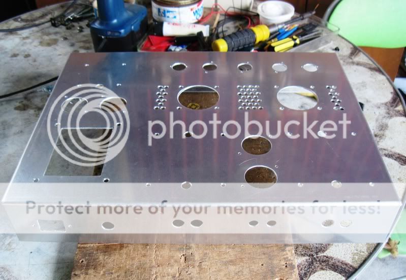
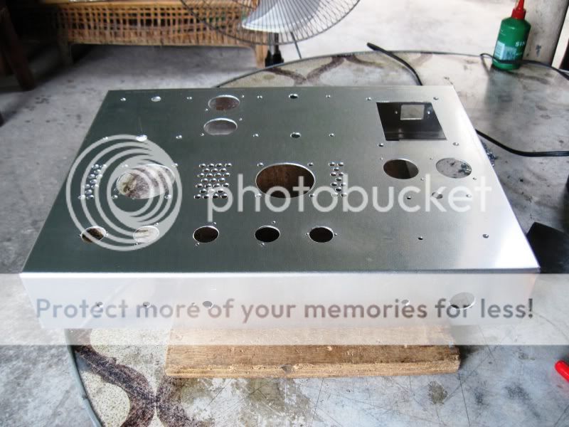
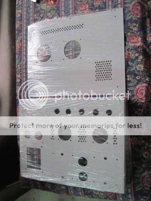
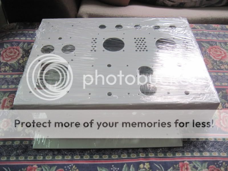
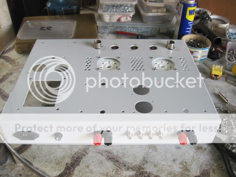
2nd installment: chassis preparation;
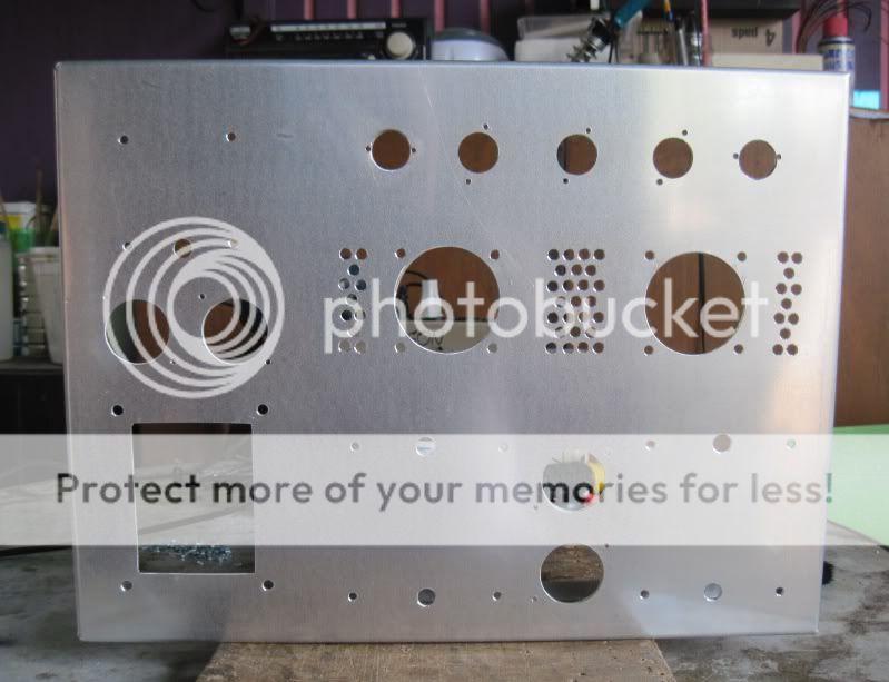
aluminum gage 14 was used, 0.075inch thick for both box and bottom plate, wooden sidings used to cover the sides...aluminum is very easy to work with, a joy to drill and quick to file out and polish....i used a half round file to make straight cut-outs....😀
after drilling and punching holes, ready for powder coating......
bottom plate:
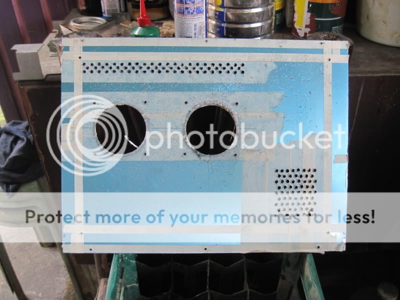
after powder coating.....
aluminum gage 14 was used, 0.075inch thick for both box and bottom plate, wooden sidings used to cover the sides...aluminum is very easy to work with, a joy to drill and quick to file out and polish....i used a half round file to make straight cut-outs....😀
after drilling and punching holes, ready for powder coating......
bottom plate:
after powder coating.....
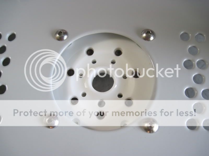
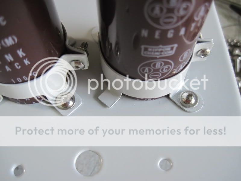
3rd installment: mounting of traffos, filter caps and sockets......
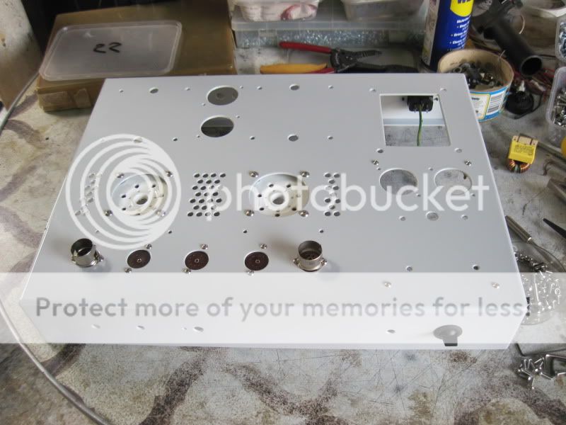
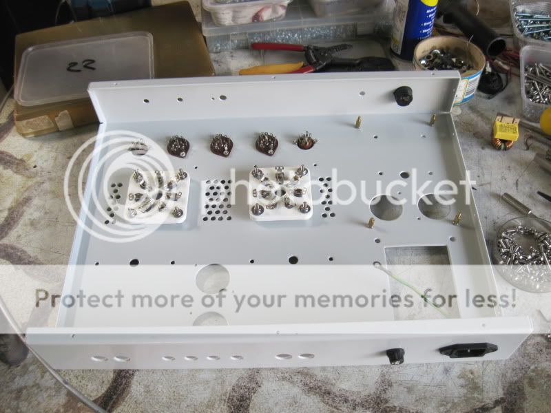
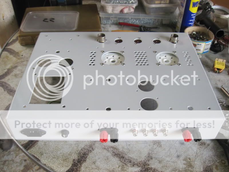
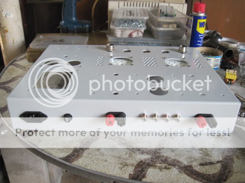
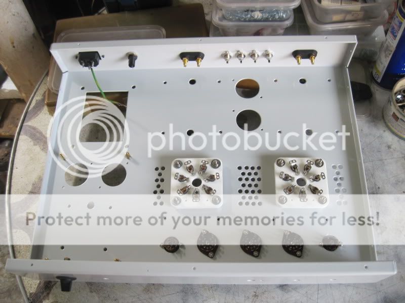
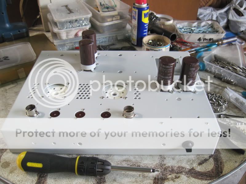
stainless steel allen key type bolts used, guaranteed rust free for the life of the amp....
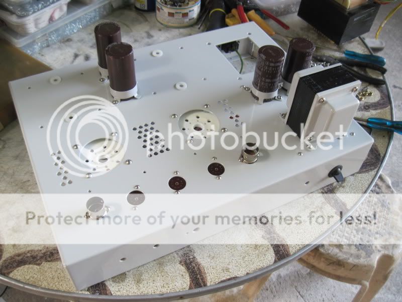
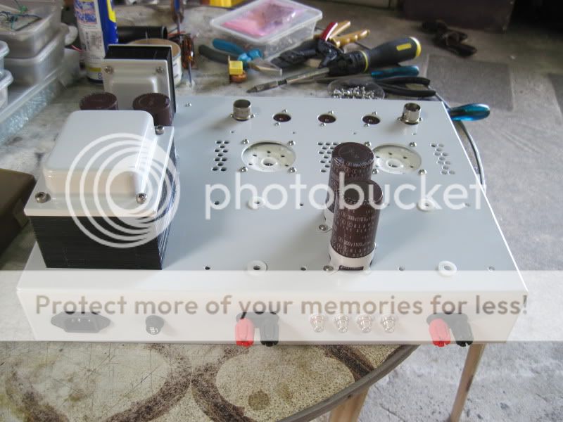
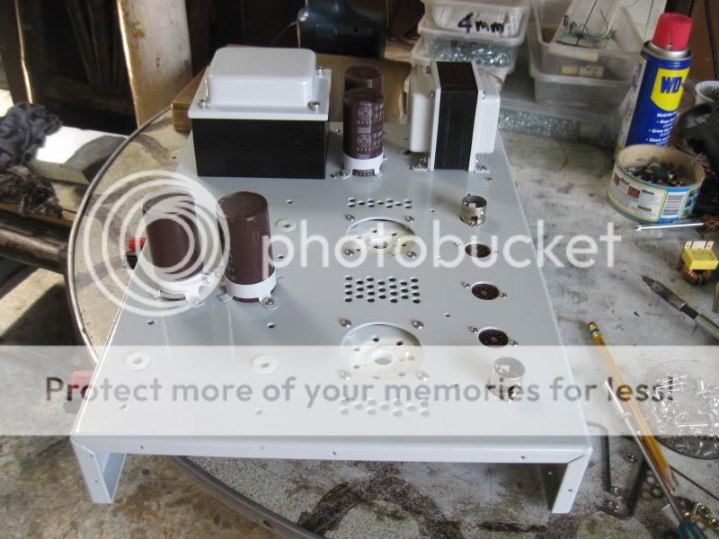
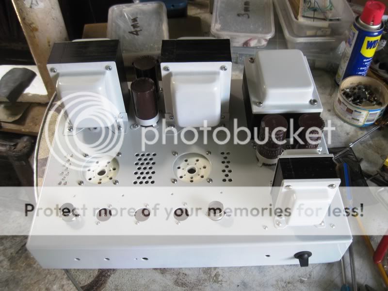
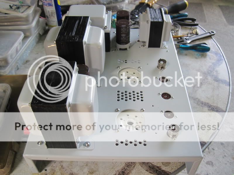
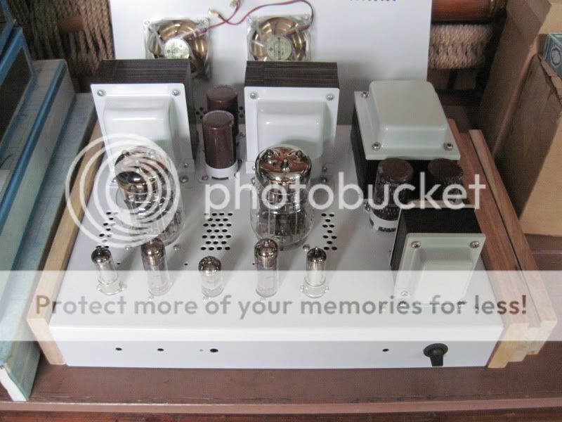
tubes fitted...
stainless steel allen key type bolts used, guaranteed rust free for the life of the amp....
tubes fitted...
excellent work, impressive build quality!
I believe he 6c33c is a beautiful tube. i plan on using it to drive a gu81m based set amp (still have two big bottles left)
http://www.moehrenbude.de/Moehre/images2/projekte/GU81_6C33C_simpel.pdf
output transformer is tricky...260mA 5k primary. Still haven't found an exact match in commercially available (and affordable) products.
anyways...great work and I like the white bells!
excellent work, impressive build quality!
I believe he 6c33c is a beautiful tube. i plan on using it to drive a gu81m based set amp (still have two big bottles left)
http://www.moehrenbude.de/Moehre/images2/projekte/GU81_6C33C_simpel.pdf
output transformer is tricky...260mA 5k primary. Still haven't found an exact match in commercially available (and affordable) products.
anyways...great work and I like the white bells!
thanks Alex, i built all the irons in this amp......there are no commercially available traffos that i know of......
indeed the 6C33 is a beautiful tube.....
wiring completion;
at the start......
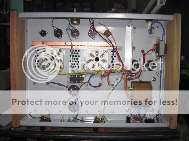
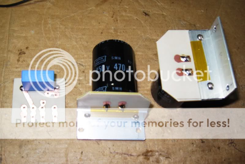
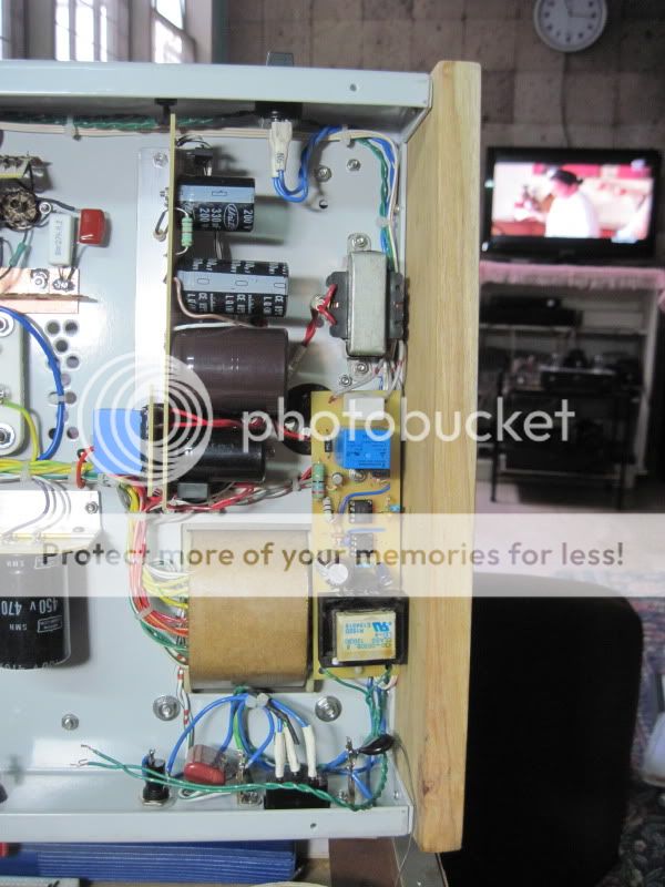
bias and high voltage dc psu board installed......
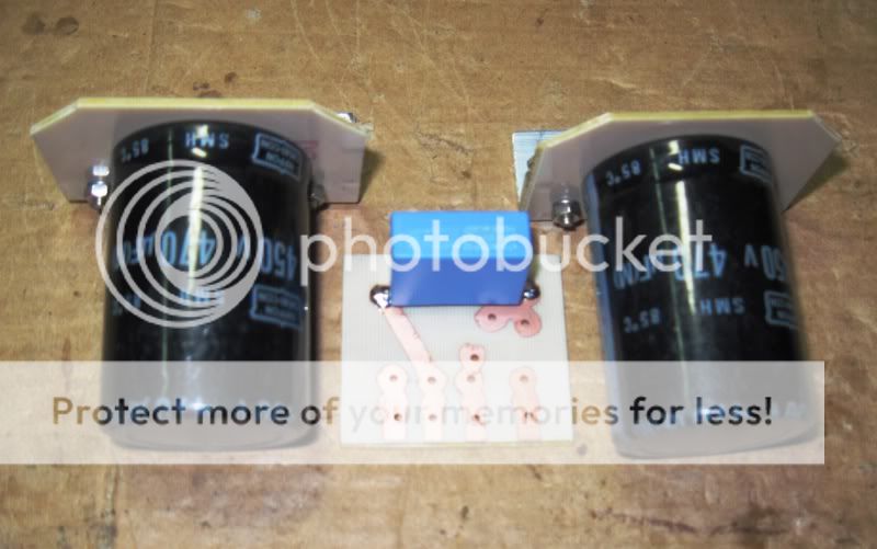
high current main B+ rectifier installed in pcb at the left, the 2 filter caps are for the 400volt dc supply to the 6P15P voltage amplifier stage....
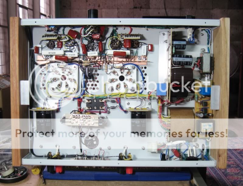
central grounding bus installed.....
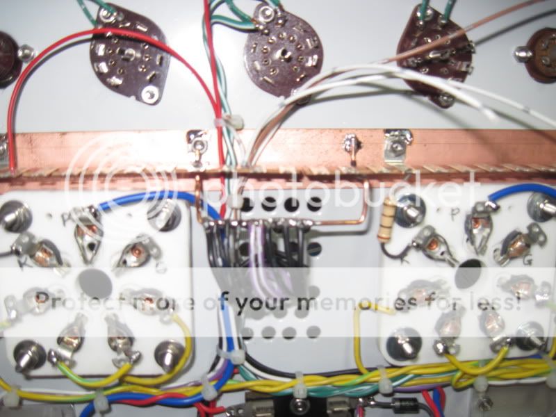
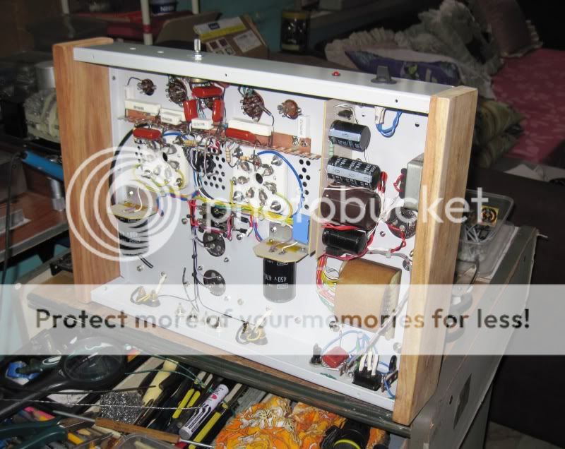
front-end wiring complete....
input tube 6P15P cathode bias uses diode string in a pcb.....
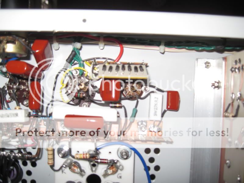
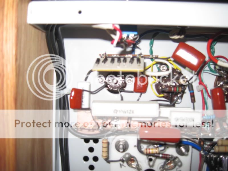
6C33 grid bias pots installed....
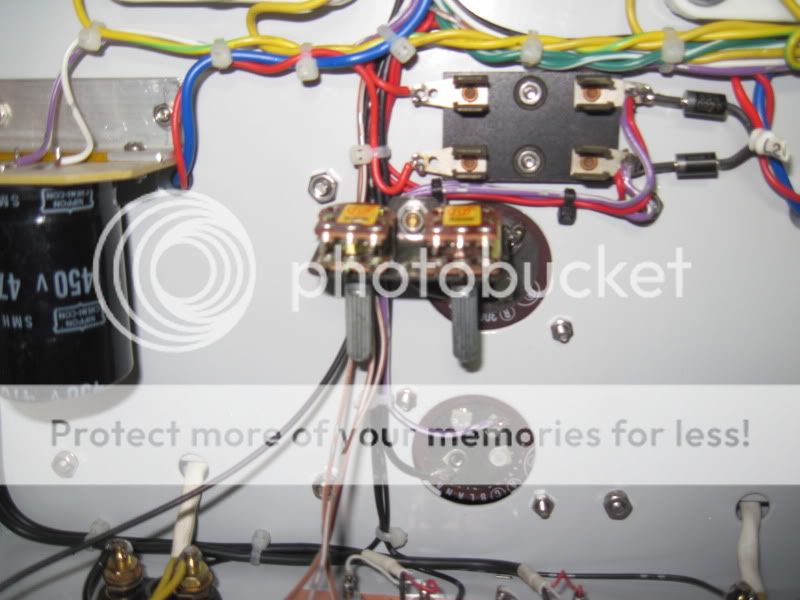
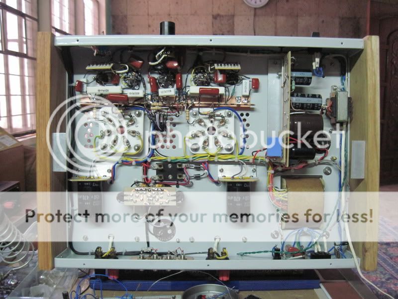
almost there......
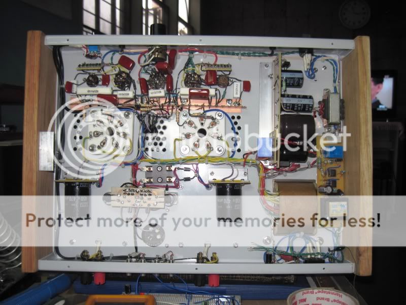
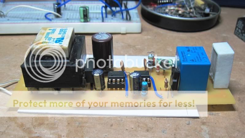
i wanted a time delay for the 6C33plates to give enough time for the filaments to get warmed up prior to application of B+ so i designed and built a 3 minute delay timer with a soft starting resistor of 12k/5watts in series with main B+ ac supply to the bridge rectifier....there is a 2 color panel led that blinks red about once each second and turns green at the end of the timing period...the 12k resistor is shorted out at this time.....
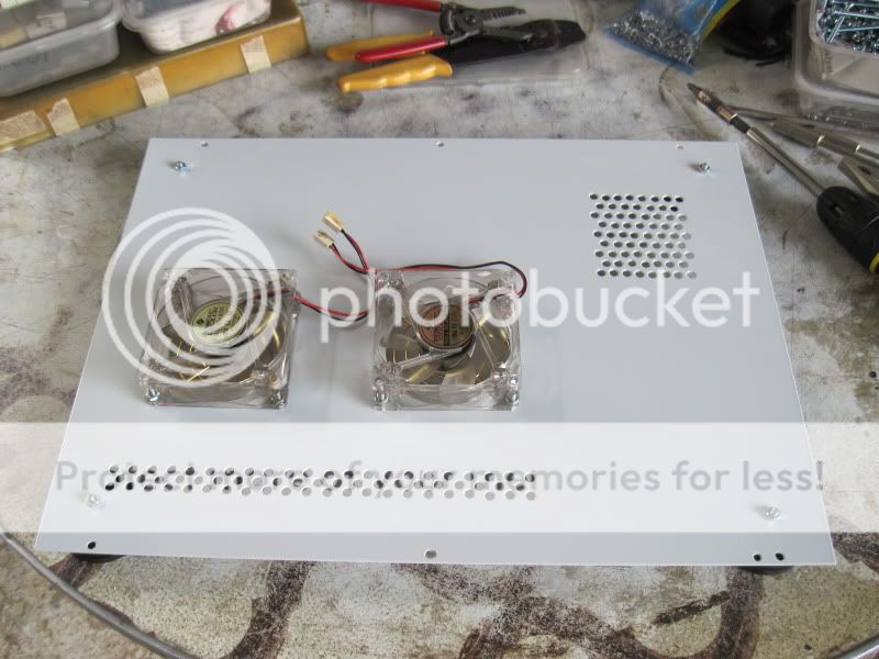
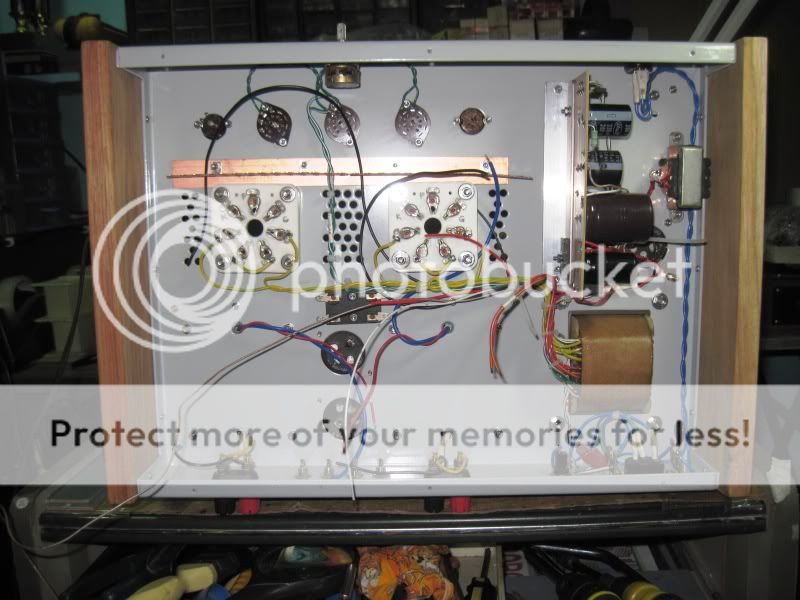
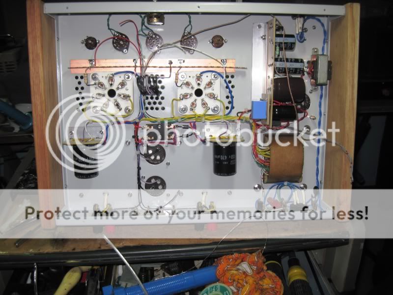
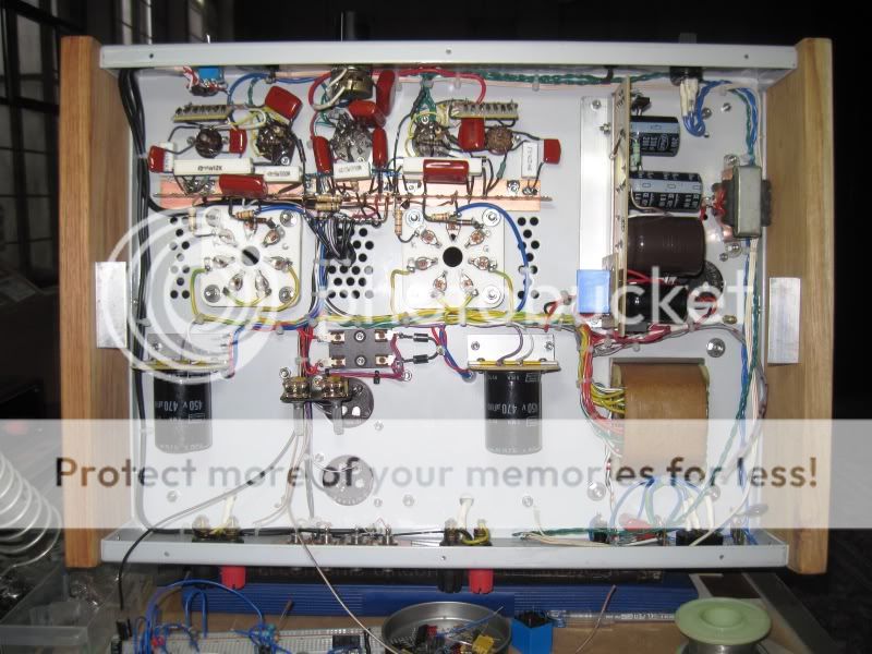
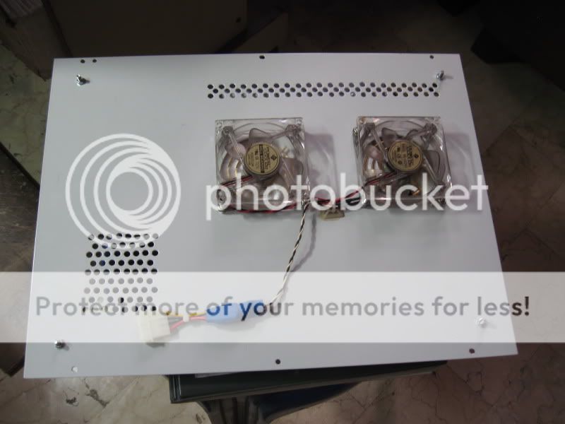
underside of the amp completed.....
the bottom plate is fitted with 2 x 12volt ball bearing fans, so mitigate potential noise, these fans are powered by 6 volt dc supplies, they move air to go past the 6C33 sockets to somehow cool them down....
at the start......
bias and high voltage dc psu board installed......
high current main B+ rectifier installed in pcb at the left, the 2 filter caps are for the 400volt dc supply to the 6P15P voltage amplifier stage....
central grounding bus installed.....
front-end wiring complete....
input tube 6P15P cathode bias uses diode string in a pcb.....
6C33 grid bias pots installed....
almost there......
i wanted a time delay for the 6C33plates to give enough time for the filaments to get warmed up prior to application of B+ so i designed and built a 3 minute delay timer with a soft starting resistor of 12k/5watts in series with main B+ ac supply to the bridge rectifier....there is a 2 color panel led that blinks red about once each second and turns green at the end of the timing period...the 12k resistor is shorted out at this time.....
underside of the amp completed.....
the bottom plate is fitted with 2 x 12volt ball bearing fans, so mitigate potential noise, these fans are powered by 6 volt dc supplies, they move air to go past the 6C33 sockets to somehow cool them down....
Wel done Sir!
You must be proud. Completing a project without commercially available products is real DIY.
Could you please take some measurements when you are finished? 🙂
Best
You must be proud. Completing a project without commercially available products is real DIY.
Could you please take some measurements when you are finished? 🙂
Best
Bravo. Most excellent work. Love the pics on the transformer winding. In fact, I love all the pictures! Thanks for sharing.
Beautiful work
Truly nice job, Tony. If the amp sounds as good as it looks, it should be really nice. Perhaps this is a run up to a GM70 project?
Truly nice job, Tony. If the amp sounds as good as it looks, it should be really nice. Perhaps this is a run up to a GM70 project?
Truly nice job, Tony. If the amp sounds as good as it looks, it should be really nice. Perhaps this is a run up to a GM70 project?
thanks, i had my eyes set on the 813 tubes ever since i saw it in our science lab while in high school, i have a quad of those but seeing the high voltages involved, i had a rethink.......
a local tube scavenger sold me a quad of QE08-200 tubes, a pair can do 300watts with just 750volts on the plates, well within the range of my dmm's....so that will be my new mount everest......😀
Wel done Sir!
You must be proud. Completing a project without commercially available products is real DIY.
Could you please take some measurements when you are finished? 🙂
Best
yes, i build my own irons for all my projects..........
will try to get some measurements when the amp is making music.....
this amp was meant to be a competition piece this July, but was postponed for November when we are having our anual HI-Fi show......😀
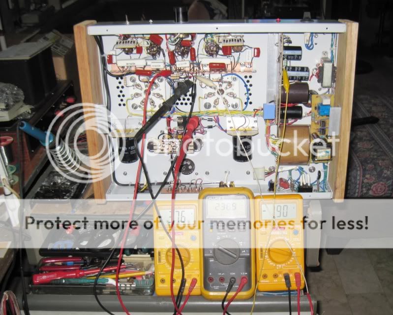
livening up......this is the term we used to call any equipment that is being turned on for the first time.....dealing with electricity, you just can't rush things up, there are certein rituals to be followed if you do not want smoke to come out......
to recap, tube complements are, CG-13 gas regulator tube equivalent to 0A2, 6N1p as input buffer stage, 6P15P as voltage amplifier and 6C33C as output tubes...
with the 6C33C, i used a 400 grit sand paper to remove tarnish on the pins and ensured good contact with the sockets..
tubes are aglow....
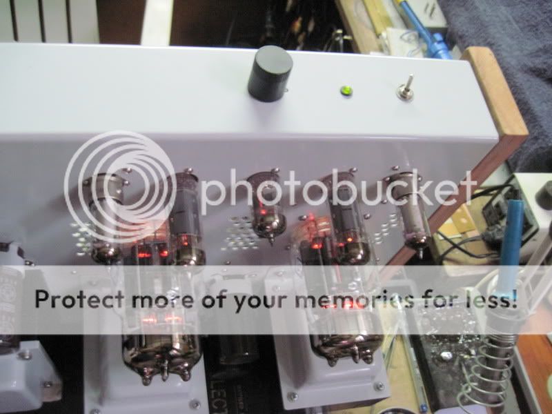
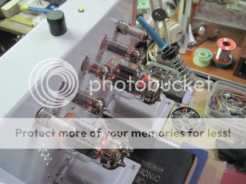
testing for voltage levels showed them to be very close to intended voltages, save the grid bias at -190volts....this is very easy to correct..
to recap, tube complements are, CG-13 gas regulator tube equivalent to 0A2, 6N1p as input buffer stage, 6P15P as voltage amplifier and 6C33C as output tubes...
with the 6C33C, i used a 400 grit sand paper to remove tarnish on the pins and ensured good contact with the sockets..
tubes are aglow....
testing for voltage levels showed them to be very close to intended voltages, save the grid bias at -190volts....this is very easy to correct..
- Status
- Not open for further replies.
- Home
- Amplifiers
- Tubes / Valves
- My Russian SET